A multifunctional smart water cup
A smart water cup, multi-functional technology, applied in the direction of drinking water utensils, etc., can solve the problems of small size, easy distraction, and water cups affecting the driver's sight, so as to achieve the effect of simple structure and improved convenience
- Summary
- Abstract
- Description
- Claims
- Application Information
AI Technical Summary
Problems solved by technology
Method used
Image
Examples
Embodiment 1
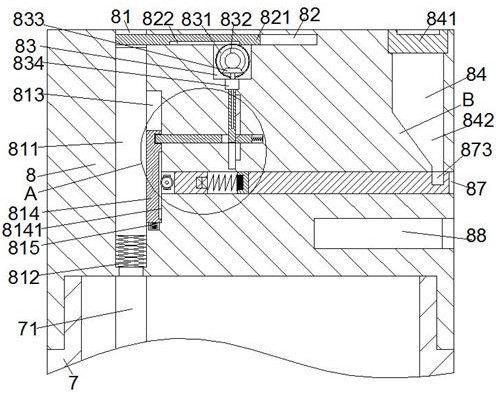
[0027] When a tablet needs to be taken, the tablet is guided and slid into the medicine-taking groove 873 by the medicine-guiding chamber 842 at the bottom of the storage cavity 84, and then the electromagnetic coil device 8713 and the magnet 8721 are controlled to generate suction force, so that the second slider 871 overcomes the first The top pressure of the spring 8712 moves to the right until the medicine taking groove 873 on the second slider 871 protrudes out of the cup cover 8 to the greatest extent, thereby realizing automatic control of taking medicine.
Embodiment 2
[0029] When it is necessary to automatically control drinking water, the second bevel gear 833 and the adjustment screw 862 are controlled by the second motor 834 to rotate, and the second bevel gear 833 drives the first bevel gear 832 and the second gear 831 to rotate, and then the second gear 831 drives The third slide block 821 slides towards the right side in the third slide chamber 82, and at the same time, the adjustment screw 862 drives the fourth slide block 861 and the inclined-plane pushing block 864 to slide downward until the left end of the third slide block 821 When completely sliding away from the telescopic slot 81, the fourth slide block 861 drives the slope on the slope pushing block 864 and the slope on the slope protrusion 8512 to be in abutting state, and continues to control the third slide block 821 toward the third slide The right direction in the cavity 82 slides. At this time, the inclined-plane pushing block 864 and the inclined-plane convex portion 8...
Embodiment 3
[0031] When the first suction pipe 811 needs to be withdrawn, the repulsive force generated by the electromagnetic coil device 8713 and the magnet 8721 is controlled, so that the second slider 871 is firmly kept in the second sliding chamber 87. At this time, the first motor 8716 is used to control the first A gear 8715 rotates, and the first gear 8715 drives the first rack 8141 and the first slider 814 to slide towards the bottom of the first sliding cavity 813, and the first slider 814 drives the first suction pipe 811 towards the telescopic groove 81 Slide inside until the first slider 814 slides to the initial position, and then the first suction pipe 811 is driven by the first slider 814 to move to the initial position. At this time, the locking groove 8142 and the fifth sliding cavity 85 are in the relative position again , and then by controlling the second motor 834 to drive the second bevel gear 833 and the adjusting screw 862 to rotate in reverse, the second bevel gea...
PUM
 Abstract
Description
Claims
Application Information
 - R&D
- Intellectual Property
- Life Sciences
- Materials
- Tech Scout
- Unparalleled Data Quality
- Higher Quality Content
- 60% Fewer Hallucinations
Browse by: Latest US Patents, China's latest patents, Technical Efficacy Thesaurus, Application Domain, Technology Topic, Popular Technical Reports.
© 2025 PatSnap. All rights reserved.Legal|Privacy policy|Modern Slavery Act Transparency Statement|Sitemap|About US| Contact US: help@patsnap.com


