Check patentability & draft patents in minutes with Patsnap Eureka AI!

Automatic lifting highway deceleration strip

A technology of automatic lifting and speed bumps, applied in the field of machinery, can solve problems such as affecting the safe passage of vehicles, tire damage, and cutting tires.

Inactive Publication Date: 2015-05-06
BEIHANG UNIV
View PDF7 Cites 17 Cited by
  • Summary
  • Abstract
  • Description
  • Claims
  • Application Information

AI Technical Summary

Problems solved by technology

[0004] Although this kind of automatic lifting road deceleration belt can achieve the purpose of forced deceleration, because the edge of the deceleration belt plate will be separated from the road surface, an edge will be formed relative to the road surface, and the vehicle must roll over this belt to pass through the deceleration belt "Edge", which will cause damage to the tire, and may seriously damage the tire and affect the safe passage of the vehicle

Method used


Image

  • Automatic lifting highway deceleration strip
  • Automatic lifting highway deceleration strip
  • Automatic lifting highway deceleration strip

Examples


Embodiment Construction

[0023] In order to make the purpose, technical solutions and advantages of the embodiments of the present invention clearer, the technical solutions in the embodiments of the present invention will be clearly and completely described below in conjunction with the drawings in the embodiments of the present invention. Obviously, the described embodiments It is a part of embodiments of the present invention, but not all embodiments. Based on the embodiments of the present invention, all other embodiments obtained by persons of ordinary skill in the art without creative efforts fall within the protection scope of the present invention.

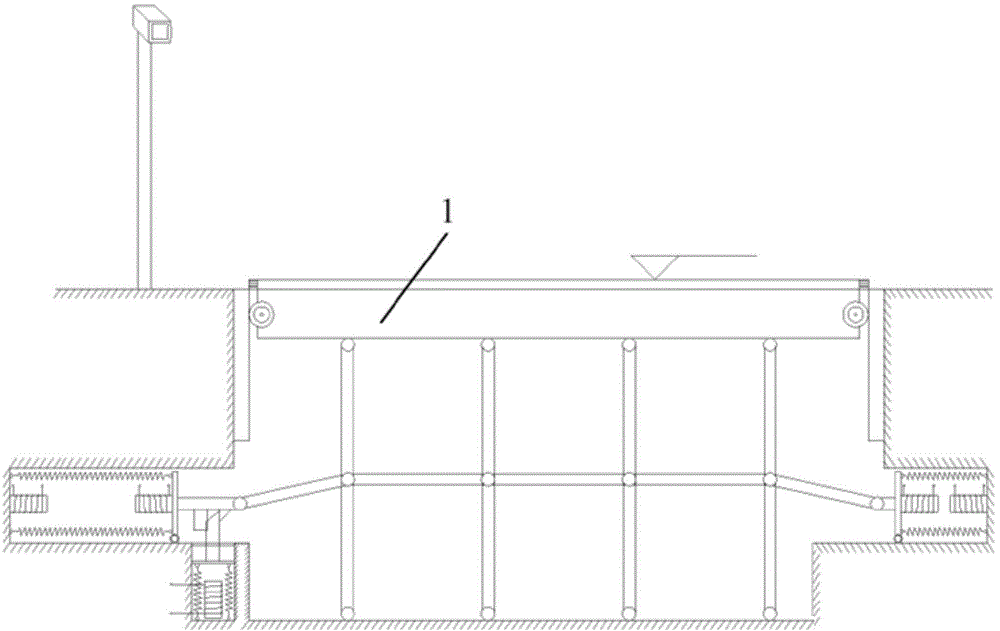
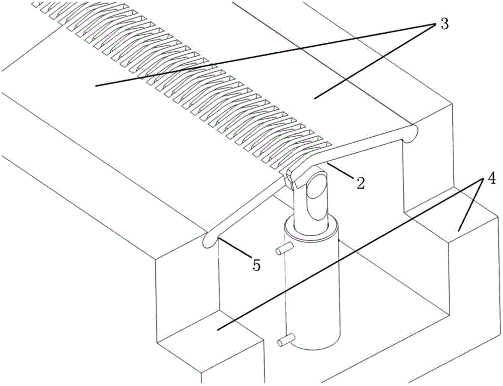
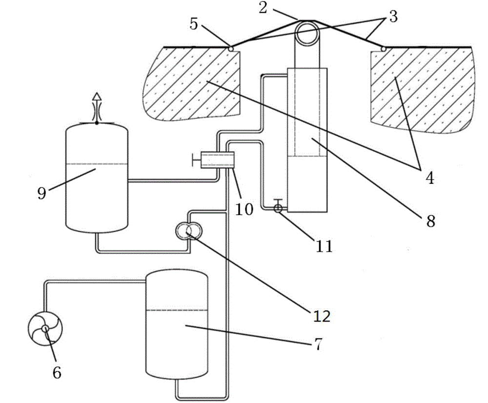
[0024] figure 2 The schematic diagram of the mechanism of the automatic lifting road deceleration belt provided by the present invention, such as figure 2 As shown, the automatic lifting road deceleration belt includes a deceleration belt 2, and the deceleration belt 2 includes two interlocking comb-shaped deceleration belt plates 3, and the tw...


PUM


Abstract

The invention provides an automatic lifting highway deceleration strip comprising a deceleration strip body. The deceleration strip body comprises two comb-shaped deceleration strip plates meshed with each other, the two side edges of the deceleration strip body are connected with rotating shafts of bases respectively, the comb-shaped deceleration strip plates can rotate along the rotating shafts of the bases, the rotating shafts of the bases and the road surface are installed on the same horizontal position, and a supporting mechanism capable of ascending and descending is arranged at the lower end of the deceleration strip body; when the supporting mechanism is in the ascending state, the deceleration strip body is in a protruding shape, and when the supporting mechanism is in the descending state, the deceleration strip body is in a flat plate shape; thus, when the running speed of a vehicle is within a limited speed, the vehicle can pass through the deceleration strip body flush with the road surface, and when the running speed of the vehicle exceeds the limited speed, the vehicle can pass through the deceleration strip body, wherein the two sides of the deceleration strip body are in smooth connection with the road surface but the middle of the deceleration strip body protrudes.

Description

technical field [0001] The invention relates to the field of machinery, in particular to an automatic lifting road deceleration belt. Background technique [0002] The automatic lifting road deceleration belt is a traffic facility installed on the road to reduce the speed of motor vehicles and non-motor vehicles. When the speed of the vehicle is within the speed limit, the deceleration belt is lowered to allow the vehicle to pass smoothly. The speed of the vehicle exceeds When the speed is limited, the speed bump is raised to make the vehicle feel bumpy and force the speed to slow down. [0003] figure 1 It is a kind of automatic lifting road deceleration belt in the prior art, such as figure 1 As shown, the deceleration belt plate 1 is set as a plane. When the vehicle approaches the deceleration belt, if the measured vehicle speed is within the speed limit, maintain the initial state that the surface of the deceleration belt plate 1 is flush with the road surface, so that...

Claims


Application Information

Patent Timeline
IPC IPC(8): E01F9/047E01F9/529
Inventor 武鹏飞程小全郭鑫王松伟刘淑峰
Owner BEIHANG UNIV
Features
  • R&D
  • Intellectual Property
  • Life Sciences
  • Materials
  • Tech Scout
  • Unparalleled Data Quality
  • Higher Quality Content
  • 60% Fewer Hallucinations
Learn More