Light-emitting element array advertising board, and column switching circuit and control method thereof

A technology of light-emitting elements and switching circuits, which is applied in the layout of electric lamp circuits, light sources, electric light sources, etc., and can solve problems such as inability to adapt to short circuits of LED elements.

Inactive Publication Date: 2015-05-06
RICHTEK TECH
View PDF5 Cites 6 Cited by
  • Summary
  • Abstract
  • Description
  • Claims
  • Application Information

AI Technical Summary

Problems solved by technology

[0006] The disadvantage of the prior art LED array billboard 200

Method used


Image

  • Light-emitting element array advertising board, and column switching circuit and control method thereof
  • Light-emitting element array advertising board, and column switching circuit and control method thereof
  • Light-emitting element array advertising board, and column switching circuit and control method thereof

Examples


Embodiment Construction

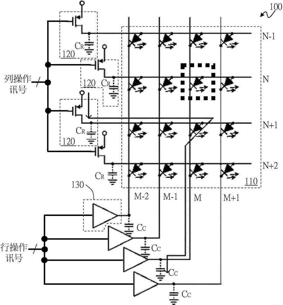
[0049] see image 3 , showing a first embodiment of the present invention. Such as image 3 As shown, the light-emitting element array billboard 300 includes a light-emitting element array circuit 310 , a plurality of column switch circuits 320 , a plurality of row driving circuits 330 , and a control circuit 340 . Wherein, the light-emitting element array circuit 310 includes a plurality of light-emitting elements 311 arranged in a plurality of rows (columns) and a plurality of columns (rows), wherein, in each column, forward ends of the plurality of light-emitting elements 311 are commonly coupled to The column node (row node), and in each row, the reverse ends of the plurality of light emitting elements 311 are commonly coupled to the row node (column node). A plurality of column switch circuits 320 are respectively coupled to a plurality of column nodes, and are used to provide column conduction voltages or discharge paths of column nodes (not shown, detailed description...


PUM


Abstract

The invention provides a light-emitting element array advertising board, and a column switching circuit and a control method thereof. The light-emitting element array advertising board comprises a light-emitting element array circuit, a plurality of column switching circuits, a plurality of row driving circuits, and a control circuit. The light-emitting element array circuit comprises a plurality of light-emitting elements which are arranged in a plurality of rows and a plurality of columns. The column switching circuits are correspondingly coupled to the columns to provide a column node column turn-on voltage or a discharge path according to a column operation signal. The row driving circuits are correspondingly coupled to the rows to provide a row node row turn-on voltage or a default level according to a row operation signal. The control circuit is coupled to the column switching circuits and the row driving circuits to provide column operation signals and row operation signals.

Description

technical field [0001] The present invention relates to a light-emitting element array billboard and its column switch circuit and its control method, in particular to a light-emitting element array billboard with the function of preventing ghost images, its column switch circuit and its control method method. Background technique [0002] Figure 1A A schematic diagram of a prior art light emitting diode (light emitting diode, LED) array billboard 100 is shown. Such as Figure 1A As shown, the LED array billboard 100 includes an LED array circuit 110 , a plurality of column switch circuits 120 , and a plurality of row drive circuits 130 . The LED array circuit 110 includes a plurality of LED elements arranged in a plurality of columns (rows) and a plurality of rows (columns). The basic operation method of the LED array billboard 100 is to use a row scanning method to sequentially supply a conduction voltage Vdd to different columns in the LED array circuit 110 in a frame,...

Claims


Application Information

Patent Timeline
IPC IPC(8): G09G3/32H05B37/02
Inventor 林水木陈庆宇林建华刘玓玓赖冠珵
Owner RICHTEK TECH
Why Eureka
Try Eureka