pay-off

A technology of pay-off device and pay-off shaft, which is applied in the field of cable pick-and-place, and can solve the problems of messy cables and slow-entry requirements for outgoing cables and other problems

Active Publication Date: 2017-10-03
WUHU HANGTIAN SPECIAL CABLE FACTORY
View PDF10 Cites 2 Cited by
  • Summary
  • Abstract
  • Description
  • Claims
  • Application Information

AI Technical Summary

Problems solved by technology

[0002] At present, in the field of taking and releasing cables, in order to ensure that the cables are not messy when taking and releasing the cables, the taking and releasing devices have been widely used. At present, mechanized operations are more extensive, and the existing taking and releasing devices cannot Matching with other equipment, for example, if the outgoing line is too fast, the cable will be messy, and the outgoing line is too slow to meet the requirements of other equipment's incoming line. Line speed is the problem that the present invention needs to solve urgently

Method used


Image

  • pay-off

Examples


Embodiment Construction

[0017] Specific embodiments of the present invention will be described in detail below in conjunction with the accompanying drawings. It should be understood that the specific embodiments described here are only used to illustrate and explain the present invention, and are not intended to limit the present invention.

[0018] In the present invention, in the absence of a contrary statement, the orientation words included in the term such as "up, down, left, right, inside, outside" only represent the orientation of the term in the normal use state, or for the purpose of A common term understood by those skilled in the art, and should not be considered as a limitation of the term.

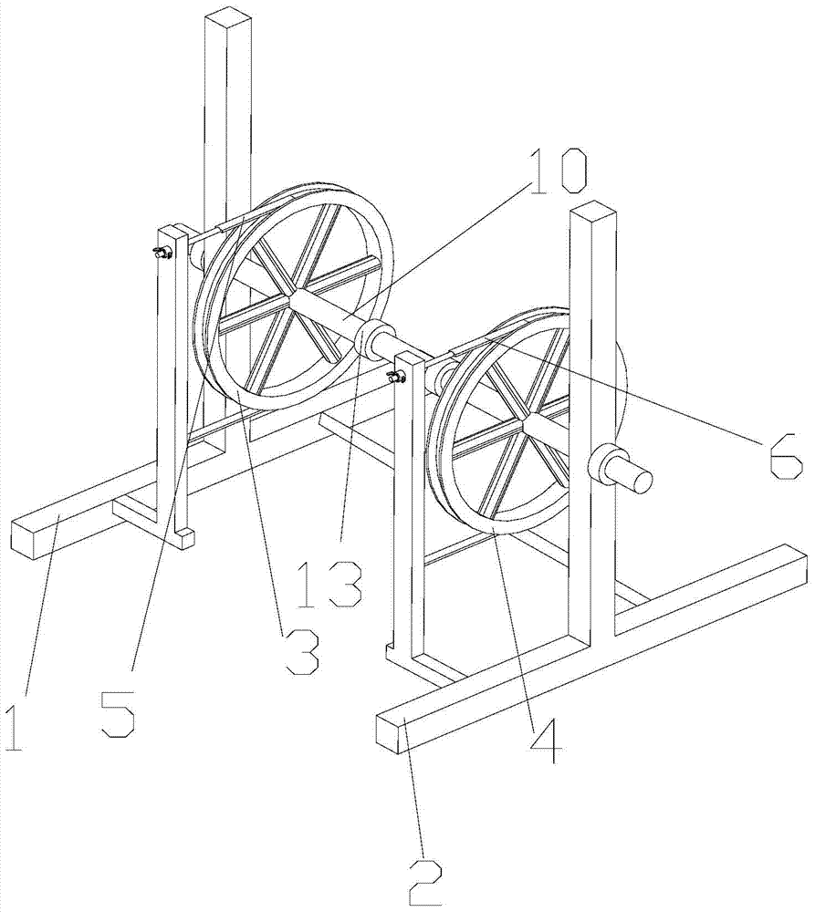
[0019] The invention provides a wire payoff, such as figure 1 As shown, the pay-off device includes a first support base 1, a second support base 2, a first runner 3, a second runner 4, a pay-off shaft 10, and a first runner mounted on the first runner 3. A speed limiting member 5 and a second spee...


PUM


Abstract

The invention discloses a wire pay-off, which comprises a first support base, a second support base, a first runner, a second runner, a pay-off shaft, and a The first speed limiting member and the second speed limiting member installed on the second runner, one end of the pay-off shaft passes through the first runner and the first support seat in turn, and the other end passes through the second runner in turn. The runner and the second support seat, the two ends of the first speed limiting member are fixedly connected to the first support seat respectively, and are set on the outer circumference of the first runner, and the second speed limiter The two ends of the speed piece are respectively fixed on the second support seat, and are sleeved on the outer circumference of the second runner. The pay-off shaft includes a plurality of connecting sections connected in sequence, and two adjacent The connecting sections are connected by a detachable connecting mechanism. This kind of wire pay-off can control the speed of taking and releasing the cable, and can better cooperate with the wire taking equipment to take the wire.

Description

technical field [0001] The invention relates to picking and placing cables, in particular to a wire releaser. Background technique [0002] At present, in the field of taking and releasing cables, in order to ensure that the cables are not messy when taking and releasing the cables, the taking and releasing devices have been widely used. At present, mechanized operations are more extensive, and the existing taking and releasing devices cannot Matching with other equipment, for example, if the outgoing line is too fast, the cable will be messy, and the outgoing line is too slow to meet the requirements of other equipment's incoming line. Line speed is the problem that the present invention needs to solve urgently. Contents of the invention [0003] The purpose of the present invention is to provide a pay-off that can control the pay-off speed, so that the pay-off can be matched with other equipment that needs cables. [0004] In order to achieve the above object, the pres...

Claims


Application Information

Patent Timeline
Patent Type & Authority Patents(China)
IPC IPC(8): B65H75/34B65H75/44
Inventor 何成龙佘晨何源杨趁芬
Owner WUHU HANGTIAN SPECIAL CABLE FACTORY
Why Eureka
Try Eureka