Electric draught fan shell

A shell and fan technology, applied in mechanical equipment, machines/engines, liquid fuel engines, etc., can solve the problems of destroying the surface plating of the pulley, bumping the surface of the pulley, and dumping the shell, and reducing bumps and damage to the surface of the pulley. Electroplating Possibility, versatility and simple structure

Inactive Publication Date: 2015-05-13
HEFEI YUANKUAN SOFTWARE INFORMATION TECH
View PDF0 Cites 0 Cited by
  • Summary
  • Abstract
  • Description
  • Claims
  • Application Information

AI Technical Summary

Problems solved by technology

[0002] The electric fan casing is one of the most important parts in the assembly process of the electric fan. At present, when the existing electric fan casing is placed, the casing is easy to fall to the side of the pulley, causing the surface of the pulley to be bumped and damaged, and the surface plating of the pulley is damaged. Therefore, it is necessary to improve the electric fan casing

Method used


Image

  • Electric draught fan shell
  • Electric draught fan shell

Examples


Embodiment Construction

[0009] The present invention will be further described below in conjunction with the accompanying drawings.

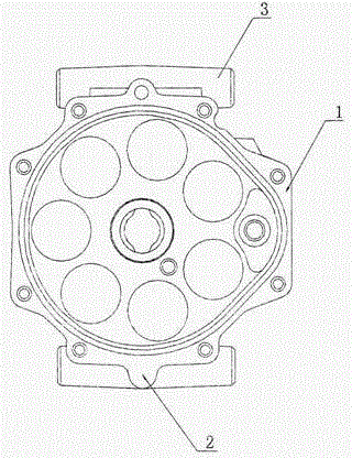
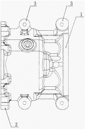
[0010] like figure 1 and figure 2 As shown, the present invention includes a housing body, and also includes cylindrical brackets 3 arranged on the left and right sides of the housing body 1, and semicircular bosses 2 arranged on the left and right sides of the housing body 1; the cylindrical brackets 3 are respectively located in the housing body. At the end and the middle, the semi-circular boss 2 is located at the tail of the housing main body 1 .

[0011] Through the semicircular boss 2 and the cylindrical bracket, the housing body 1 is more stable when placed, and the fan can be prevented from tipping to one side. It can help the fan to be placed stably and reduce the possibility of bumping the surface of the pulley and destroying the plating on the surface of the pulley.


PUM


Abstract

The invention relates to an electric draught fan, in particular to an electric draught fan shell. The electric draught fan shell comprises a shell body. The electric draught fan shell is characterized by comprising cylinder supports and half-round bosses in addition, wherein the cylinder supports are arranged on the left and right sides of the shell body, and the half-round bosses are arranged on the left and right sides of the shell body, the cylinder supports are arranged on the end and the middle of the shell body respectively, and the half-round bosses are arranged on the tail portion of the shell body. Compared with the prior art, not only is the electric draught fan shell simple in structure and strong in universality, but also can effectively prevent the shell falling towards the side of a belt pulley, be beneficial to steadily placing the draught fan, and reduce the possibilities of damaging the belt pulley surface by bumping and destroying electroplating of the belt pulley surface.

Description

technical field [0001] The invention relates to an electric fan, in particular to an electric fan casing. Background technique [0002] The casing of the electric fan is one of the most important parts in the assembly process of the electric fan. When the existing casing of the electric fan is placed, the casing is easy to fall to the side of the pulley, causing the surface of the pulley to be bumped and damaged. Therefore, it is necessary to improve the casing of the electric fan. SUMMARY OF THE INVENTION [0003] In order to overcome the deficiencies of the prior art, the present invention provides an electric fan casing. [0004] In order to achieve the above purpose, the present invention designs an electric fan casing, which includes a casing body, and is characterized in that: it also includes cylindrical brackets disposed on the left and right sides of the casing main body, and semicircular convexes disposed on the left and right sides of the casing main body. The...

Claims


Application Information

Patent Timeline
Patent Type & Authority Applications(China)
IPC IPC(8): F04D29/40
CPCF04D29/403
Inventor 马建
Owner HEFEI YUANKUAN SOFTWARE INFORMATION TECH
Why Eureka
Try Eureka