projector

A technology for projectors and synchronous signals, applied in the field of projectors, can solve problems such as increasing the amount of light, and achieve the effects of high brightness, long life, and small etendue

Inactive Publication Date: 2016-10-05
NEC DISPLAY SOLUTIONS LTD
View PDF9 Cites 0 Cited by
  • Summary
  • Abstract
  • Description
  • Claims
  • Application Information

AI Technical Summary

Problems solved by technology

However, light sources using LEDs are difficult to increase the amount of light without increasing the light emitting area

Method used


Image

  • projector
  • projector
  • projector

Examples


Embodiment Construction

[0031] In the following, exemplary embodiments are described with reference to the accompanying drawings.

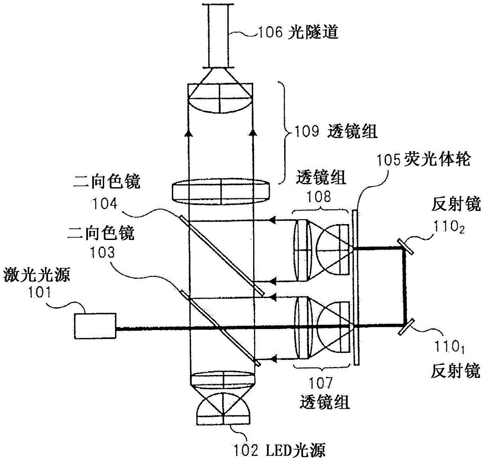
[0032] figure 1 is a block diagram illustrating the configuration of an exemplary embodiment of the illumination optical system according to the present invention.

[0033] This exemplary embodiment includes a laser light source 101, an LED light source 102, dichroic mirrors 103 and 104, a phosphor wheel 105, a light tunnel (light tunnel) 106, lens groups 107 to 109, and a mirror 110 1 and 110 2 .

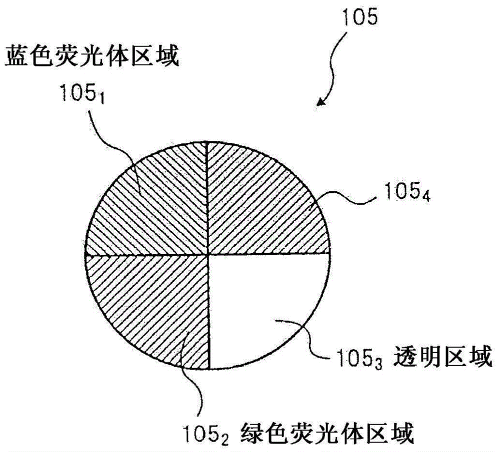
[0034] figure 2 is when from figure 1 A plan view of phosphor wheel 105 as viewed from the left side towards the right side.

[0035] The laser light source 101 generates excitation laser light having a wavelength λ1. Phosphor wheel 105 includes blue phosphor regions 105 1 and green phosphor area 105 2 and 105 4 , when the excitation laser light is incident on it, the blue phosphor region 105 1 and green phosphor area 105 2 and 105 4 Blue fluorescence and green f...


PUM


Abstract

The invention discloses a projector in a lighting optical system. The projector comprises a laser source, a synchronizing signal processor, a laser driver, an LED light source, a rotation state detector and a phosphor wheel driver. The synchronous signal processor converts synchronizing signals synchronized with video signals input from the outside into video signals used in the projector. The laser driver controls the lighting state of the laser source according to the synchronizing signals output by the synchronizing signal processor. The LED driver controls the lighting state of the LED light source according to the synchronizing signals output by the synchronizing signal processor. The rotation state detector detects the rotation state of a phosphor wheel. The phosphor wheel driver controls the rotation state of the phosphor wheel according to the detection result of the rotation state detector, so that the color of one indication video signal in the synchronizing signals output by the synchronizing signal processor is matched with the color which is output by the lighting optical system and indicates the rotation state of the phosphor wheel, which is detected by the rotation state detector.

Description

[0001] This application is a divisional application of the Chinese invention patent application with the application date of January 29, 2010, the title of the invention is "Illumination Optical System and a Projector Using the Illumination Optical System", and the application number is: 201080062746.5. technical field [0002] The present invention relates to an illumination optical system that generates illumination light of various colors to form image light of various colors, and a projector that projects the image light generated by the illumination optical system. Background technique [0003] A technology using LED (Light Emitting Diode) as a light source of a projector such as a liquid crystal projector or a DMD (Digital Micromirror Device) projector that projects an image on a screen has attracted attention (see Patent Document 1). [0004] Since LEDs have a long life and provide high reliability, projectors employing LEDs as light sources have advantages of long lif...

Claims


Application Information

Patent Timeline
Patent Type & Authority Patents(China)
IPC IPC(8): G03B21/00G03B21/14
CPCG03B21/006G03B21/2013G03B21/2033G03B21/204
Inventor 齐藤裕之加藤厚志宇都宫基恭大坂明弘松原正晃
Owner NEC DISPLAY SOLUTIONS LTD
Why Eureka
Try Eureka