Circuit board positioning device and mounting method of LED placement machine

A technology of LED placement machine and positioning device, which is applied in the direction of assembling printed circuits with electrical components, and can solve the problems of uncorrectable parts tilt, low efficiency, and increased labor costs.

Inactive Publication Date: 2018-02-27
SHENZHEN TONGLISHENG PHOTOELECTRIC EQUIP
View PDF9 Cites 0 Cited by
  • Summary
  • Abstract
  • Description
  • Claims
  • Application Information

AI Technical Summary

Problems solved by technology

[0002] When the existing LED placement machine is performing placement, the nozzle head sticks to the material one by one, and it cannot perform multiple placements for different spacings of the materials, resulting in low efficiency, and the machine cannot automatically perform automatic placement if the material board is not placed. Correction, the tilt of parts cannot be corrected
Correction can only be done manually, which will result in low production efficiency, increased labor costs, and increased operational risks

Method used


Image

  • Circuit board positioning device and mounting method of LED placement machine
  • Circuit board positioning device and mounting method of LED placement machine
  • Circuit board positioning device and mounting method of LED placement machine

Examples


Embodiment 1

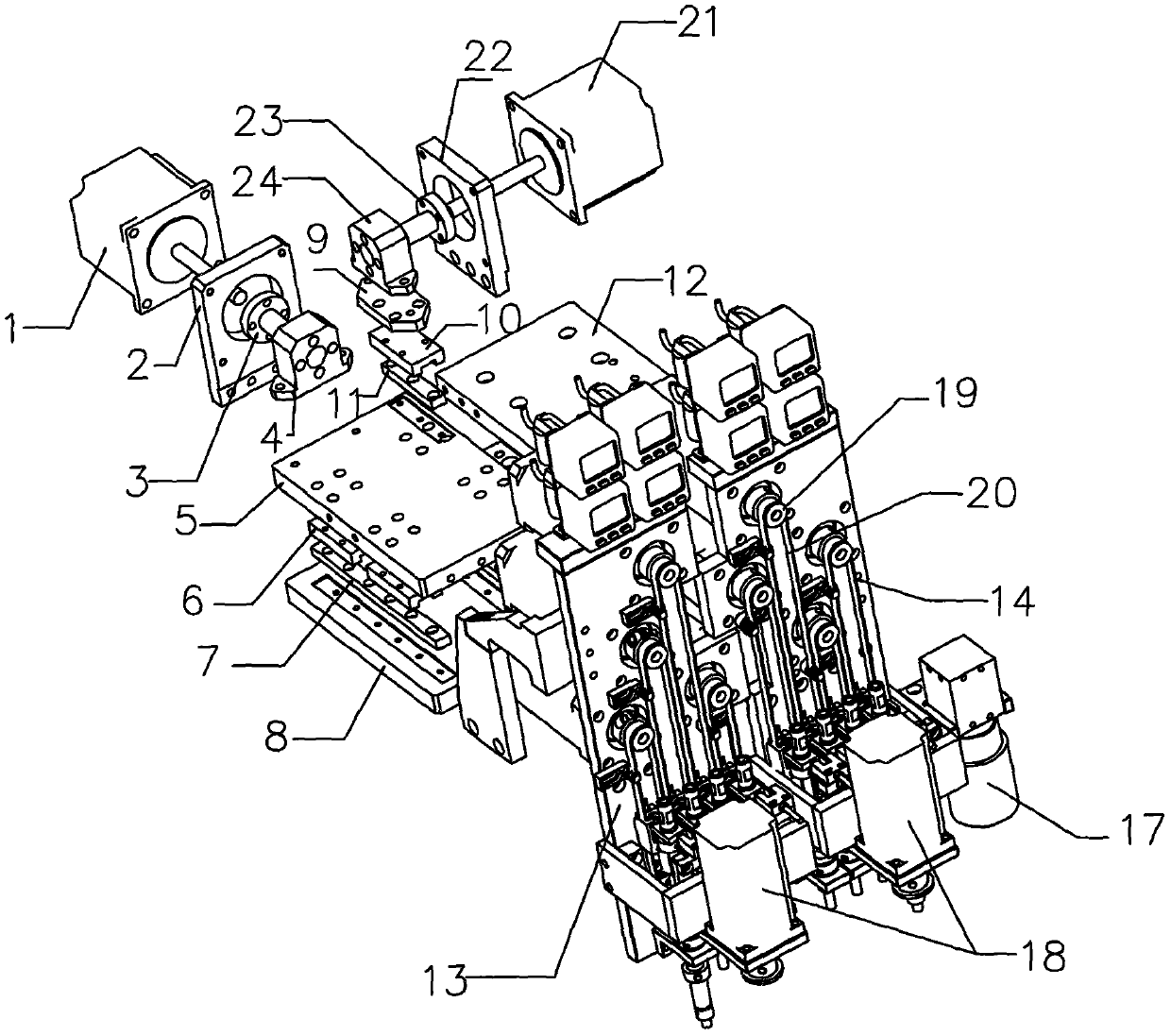
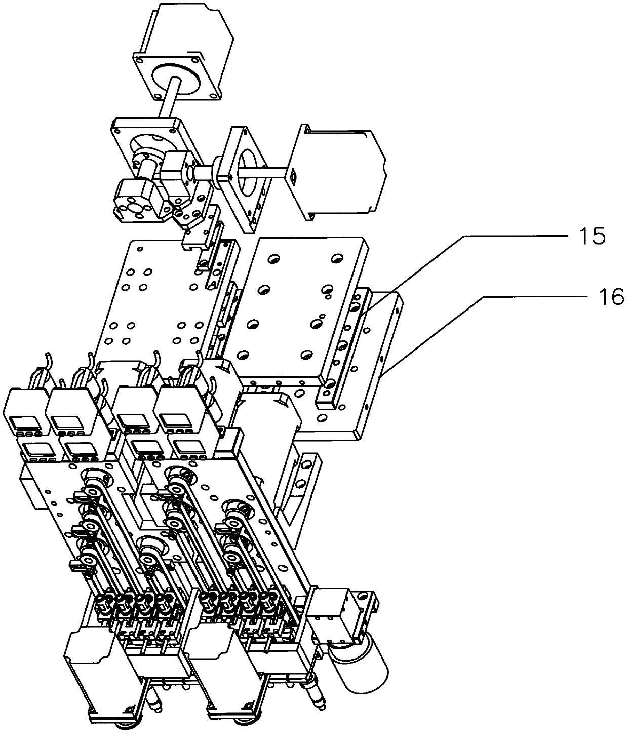
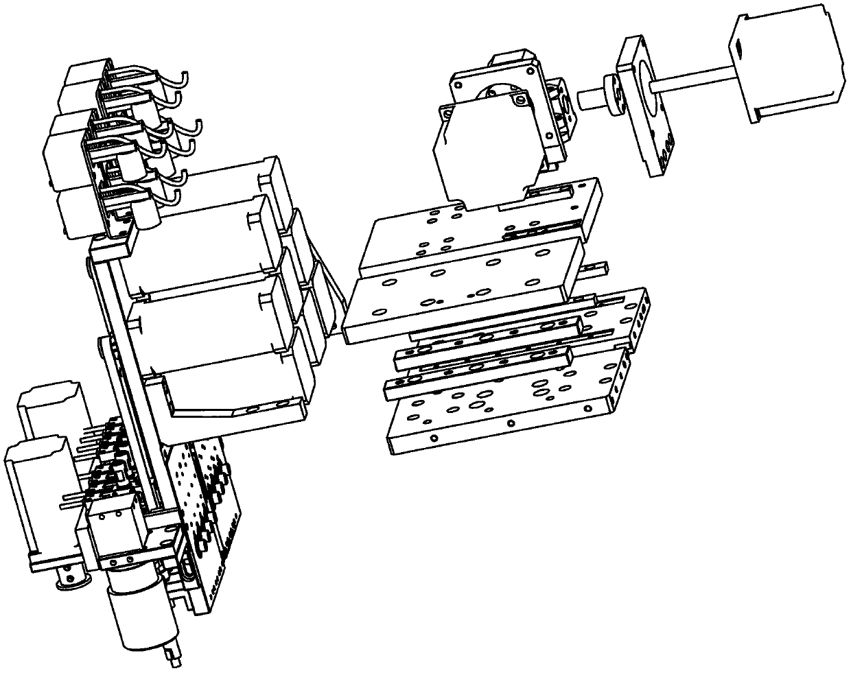
[0031] Such as Figure 1-3 As shown, the circuit board positioning device of the LED placement machine in this embodiment. It includes at least two groups of panel components, and each group of panel components is connected to a group head; each group head is connected with a front and rear drive motor 18 that controls its forward and backward movement; every two group heads are connected with a horizontal drive that controls the horizontal distance between the group heads motor17.

[0032] The panel assembly includes a first panel assembly and a second panel assembly; the group head includes a left Z group head 13 linked with the first panel assembly; a right Z group head 14 linked with the second panel assembly; one side of the right Z group head 14 is fixed A horizontal drive motor 17 that controls the horizontal distance between the left Z group head 13 and the right Z group head 14 is installed; the left Z group head 13 and the right Z group head 14 bottom end faces each...

Embodiment 2

[0039] Such as Figure 4 As shown, this embodiment discloses a method for mounting the circuit board positioning device of the LED chip mounter of the present invention, including steps:

[0040] Start the placement process;

[0041]Query the remaining points of placement; if the remaining points of placement are less than 2, mount them separately until the remaining points are zero, and complete the placement process once; if the remaining points are greater than or equal to 2, go to the following steps;

[0042] Calculate the offset of the placement point;

[0043] Correct the positional offset of the components;

[0044] Perform placement operations on at least two components at the same time; until the remaining points are zero, complete a placement process.

[0045] Such as Figure 5 As shown, this method also includes the mounting steps of components:

[0046] Mark and position the circuit board of the component;

[0047] Query the unmounted point; if the placement...


PUM


Abstract

The invention discloses a circuit board locating device of an LED chip mounter and a mounting method thereof. The circuit board locating device of the LED chip mounter comprises at least two groups of panel components, and each group of panel components is correspondingly connected with a group head; each group head is connected with a transverse drive motor for controlling the transverse move thereof; each two group heads are connected with a horizontal drive motor for controlling the horizontal space between the group heads. Because the circuit board locating device of the LED chip mounter uses the horizontal drive motor, transverse drive motor and at least two groups of group heads, the horizontal drive motor can regulate the space between two adjacent groups of group heads so as to enable the circuit board locating device to adapt to different distances of elements, and the circuit board locating device is capable of regulating the distance between two group heads to be corresponding to different distances between materials to perform chip mounting for the circuit board. The transverse drive motor is capable of transversely moving the group head to correct materials, for example, when materials on the panel are placed in a crooked state (one is located at the front while the other is located at the back), the materials can be corrected through the fine adjustment of the transverse drive motor.

Description

technical field [0001] The invention relates to the field of electronic product manufacturing, and more specifically relates to a circuit board positioning device of an LED placement machine and a placement method thereof. Background technique [0002] When the existing LED placement machine is performing placement, the nozzle head sticks to the material one by one, and it cannot perform multiple placements for different spacings of the materials, resulting in low efficiency, and the machine cannot automatically perform automatic placement if the material board is not placed. Correction, the tilt of parts cannot be corrected. It can only be corrected manually, which will result in low production efficiency, increased labor costs, and increased operational risks. Contents of the invention [0003] The technical problem to be solved by the present invention is to provide a circuit board positioning device and a mounting method of an LED chip mounter with improved efficiency...

Claims


Application Information

Patent Timeline
Patent Type & Authority Patents(China)
IPC IPC(8): H05K3/30
CPCH05K3/30
Inventor 吴盛龙
Owner SHENZHEN TONGLISHENG PHOTOELECTRIC EQUIP
Why Eureka
Try Eureka