Calibration device for invoice printing
A correction device and invoice technology, applied in printing, printing machines, rotary printing machines, etc., can solve problems affecting the quality of invoices, paper wear, etc.
- Summary
- Abstract
- Description
- Claims
- Application Information
AI Technical Summary
Problems solved by technology
Method used
Image
Examples
Embodiment Construction
[0019] The following is further described in detail through specific implementation methods:
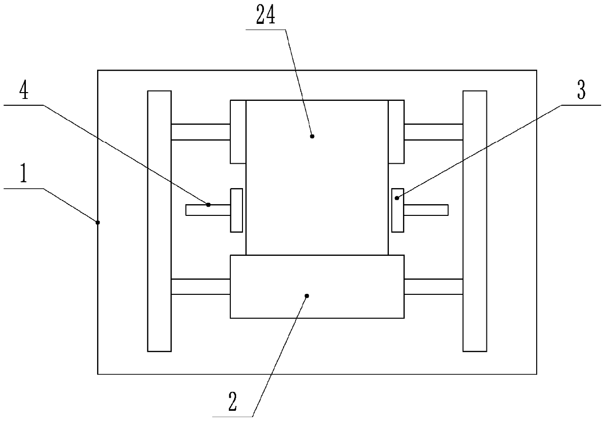
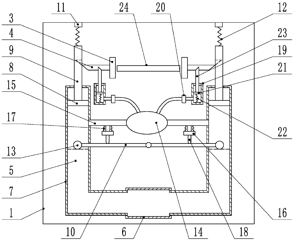
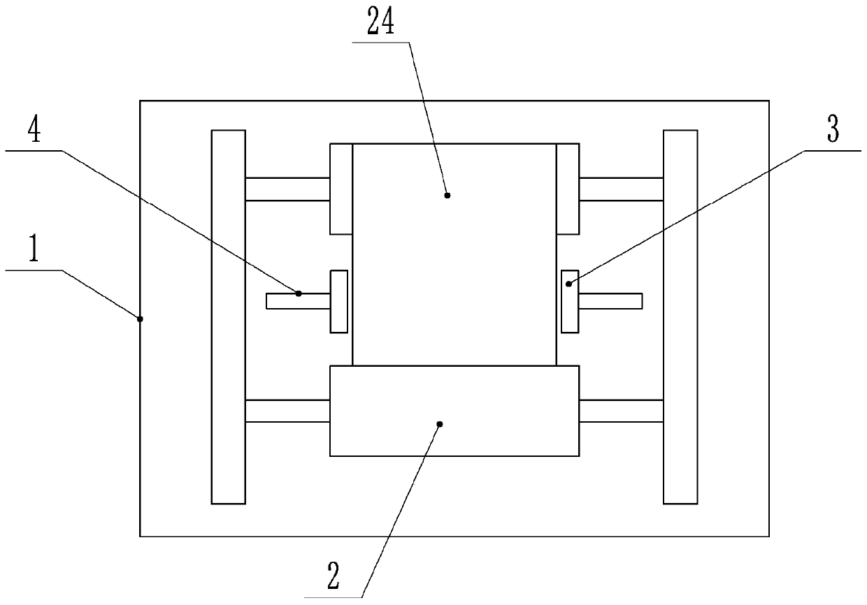
[0020] The reference signs in the drawings of the description include: frame 1, guide roller 2, correction plate 3, first wedge bar 4, U-shaped tube 5, straight tube 6, "L"-shaped tube 7, first piston 8, The first piston rod 9, the balance rod 10, the slide block 11, the third spring 12, the buoy 13, the air bag 14, the conduit 15, the valve 16, the first spring 17, the ejector rod 18, the gas cylinder 19, the one-way valve 20, the second Piston 21, second spring 22, second wedge bar 23, paper 24.
[0021] The embodiment is basically as attached figure 1 , figure 2 Shown:
[0022] The correction device for invoice printing includes a frame 1, on which two guide rollers 2 for transporting paper 24 are rotatably connected. side and slidingly connected to the correction plate 3 on the frame 1, the side of the correction plate 3 in contact with the paper 24 is covered with a slippin...
PUM
 Abstract
Description
Claims
Application Information
 - R&D
- Intellectual Property
- Life Sciences
- Materials
- Tech Scout
- Unparalleled Data Quality
- Higher Quality Content
- 60% Fewer Hallucinations
Browse by: Latest US Patents, China's latest patents, Technical Efficacy Thesaurus, Application Domain, Technology Topic, Popular Technical Reports.
© 2025 PatSnap. All rights reserved.Legal|Privacy policy|Modern Slavery Act Transparency Statement|Sitemap|About US| Contact US: help@patsnap.com


