

Induction device to limit acoustic oscillations
A technology of induction devices and windings, applied in the direction of circuit devices, transformer/inductor noise damping, electrical components, etc., can solve problems such as incompatibility, expensive design requirements for solutions, etc., and achieve the effect of reducing vibration
- Summary
- Abstract
- Description
- Claims
- Application Information
AI Technical Summary
Problems solved by technology
Method used
Image

Examples
Embodiment Construction
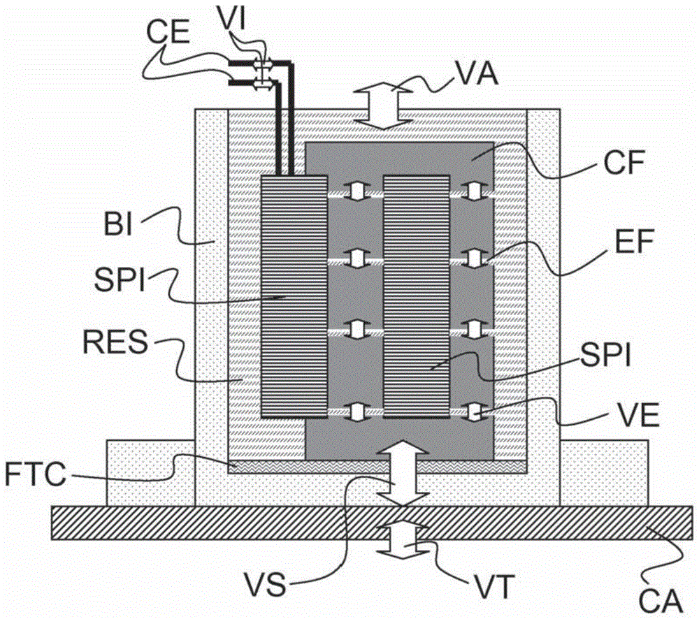
[0023] According to a preferred embodiment of the invention shown in the drawings, the induction device according to the invention has a housing BI formed by an aluminum can. The housing BI is fastened at its lower base by four screws to the housing CA protecting the power electronics module of the electric vehicle charger in the region of the housing CA cooled by the charger's cooling system. This is because in this embodiment of the invention an inductive device is used as inductive for the electric vehicle charger.
[0024] The winding SPI is held vertically in the longitudinal direction within the housing BI and is connected to electrical connectors CE through which high currents with a current variation VI enter and leave when the induction device is used. A ferromagnetic body CF is partially inserted into the winding SPI. The ferromagnetic body is composed of a plurality of ferromagnetic blocks (for example ferrite blocks) separated by a gap EF placed transversely with ...
PUM
| Property | Measurement | Unit |
|---|---|---|
| thickness | aaaaa | aaaaa |
| hardness | aaaaa | aaaaa |
| hardness | aaaaa | aaaaa |
Abstract
Description
Claims
Application Information