A co-rotational flotation smelting method, nozzle and metallurgical equipment

A technology of nozzles and cyclones, which is applied in the field of obtaining sulfur and even metal products from metal sulfide concentrate powder, can solve the problem of large differences in physical specifications, specific gravity, and chemical composition properties, the inability of concentrate particles to be oxidized, and the difficulty of swirl strength. Control and other issues to achieve the effect of no reaction dead zone, small reaction space and large production capacity

Active Publication Date: 2016-09-14
YANGGU XIANGGUANG COPPER
View PDF11 Cites 2 Cited by
  • Summary
  • Abstract
  • Description
  • Claims
  • Application Information

AI Technical Summary

Problems solved by technology

However, the above-mentioned method has the following problems in production practice: due to the excessive entrainment of the cyclone fluid, a large amount of high-temperature flue gas after the reaction is returned to the top of the reaction tower, causing the loss of the top of the reaction tower to be too fast; for individual concentrate particles, the Physical specifications, specific gravity, chemical composition and other properties are quite different. The swirl intensity can be adjusted but it is difficult to control. If it is too small, it is not enough to drive the particles to rotate. If it is too large, flashing will appear and damage the furnace body; the reaction gas flows from the inside to the outside. Diffusion, when reaching the outer ring of the material ring, most of the oxygen has been consumed, resulting in the concentrate particles in the outer ring of the material ring cannot be oxidized

Method used


Image

  • A co-rotational flotation smelting method, nozzle and metallurgical equipment
  • A co-rotational flotation smelting method, nozzle and metallurgical equipment

Examples


Embodiment Construction

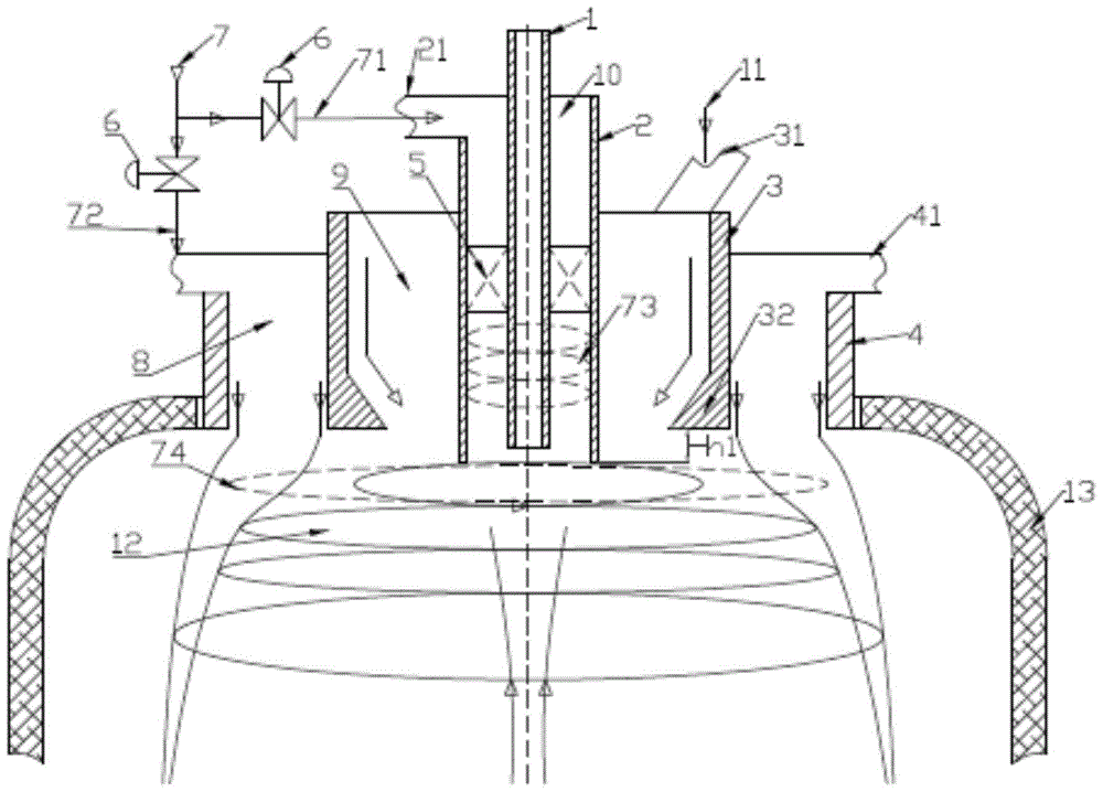
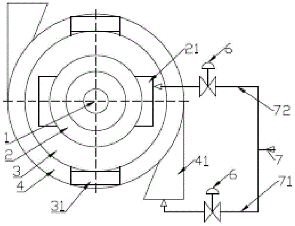
[0035] The invention discloses a new co-rotating flotation smelting method to improve the utilization rate of oxygen and make the material react with oxygen completely; it overcomes the flashing phenomenon of the swirling flow and the reflux phenomenon of a large amount of high-temperature flue gas in the outer ring, and the required The reaction space is small, there is no reaction dead zone, and the erosion of the refractory material of the furnace body is small. The invention provides a co-rotating buoyant smelting nozzle for realizing the above method, and a metallurgical equipment using the above nozzle.

[0036] The following will clearly and completely describe the technical solutions in the embodiments of the present invention with reference to the accompanying drawings in the embodiments of the present invention. Obviously, the described embodiments are only some, not all, embodiments of the present invention. Based on the embodiments of the present invention, all oth...


PUM


Abstract

The invention discloses a same-direction rotary-floating smelting method. The method includes that powdery sulphide concentrate and oxygen-containing gas are sprayed into space of a high-temperature reaction tower through equipment; the oxygen-containing gas is divided into two parts before entering the equipment, and second oxygen-containing gas is sprayed into the reaction tower by means of annular rotational flow to form a bell-shaped rotating air curtain; first oxygen-containing gas is converted into rotary jet flow through the equipment and injected at the center of the rotating air curtain; in an annular space between two branches of the rotating air flow, the concentrate enters in a direction deflecting to the center, is drawn into by the oxygen-containing gas and sucks high-temperature smoke on the lower portion of the reaction tower to form two-phase rotating jet flow with gas and particle mixed; when being ignited by high temperature, the sulphide concentrate is in drastic burning reaction with oxygen and releases SO2-enriched smoke and forms mixed melt containing sulfonium (or metal) and slag, and sulfonium (or metal) and slag are separated at the bottom of the reaction tower to complete metallurgical process. The invention further provides metallurgical equipment and a same-direction rotary floating smelting nozzle thereof.

Description

technical field [0001] The invention relates to the technical field of nonferrous metallurgy, in particular to a method and equipment for smelting concentrate powder containing metal sulfides such as copper, nickel, lead and zinc to obtain sulfur and even metal products. Background technique [0002] In the pyrometallurgical industry, smelting sulfide concentrate is the process of using the sulfur and iron in the sulfide ore to react with oxygen and finally be removed to obtain metals. The pyrometallurgical process can be roughly divided into two categories: molten pool smelting and space smelting. The essence of space suspension smelting is to use the huge surface area of ​​dried powdery sulfide ore to fully combine material particles with oxygen. seconds) to complete the oxidation reaction. The most widely used space suspension smelting is the Outokumpu flash smelting invented by Finnish scientists in 1949. The core of the process is the direct current injection technolog...

Claims


Application Information

Patent Timeline
Patent Type & Authority Patents(China)
IPC IPC(8): F27B17/00F27D3/18
Inventor 刘卫东周松林
Owner YANGGU XIANGGUANG COPPER
Why Eureka
Try Eureka