Card storage box, automatic card issuer and method for increasing card storage capacity of the automatic card issuer

An automatic card issuing and card storage box technology, which is applied to computer parts, instruments, transmission record carriers, etc., can solve the problems of increasing the friction resistance of the bottom card, limited rated load of the drive motor, and hindering the normal operation of the parking lot, etc., to achieve reduction The effect of daily maintenance workload, reduced maintenance workload, and stable work

Active Publication Date: 2017-11-14
GUANGDONG ANJUBAO INTELLIGENT CONTROL SYST
View PDF4 Cites 0 Cited by
  • Summary
  • Abstract
  • Description
  • Claims
  • Application Information

AI Technical Summary

Problems solved by technology

However, the existing automatic card issuing machines rely on the driving motor to automatically send out the cards at the bottom. Since the upper card will exert a certain pressure on the bottom card, and the rated load of the driving motor is limited, the general design capacity of the card storage box of the existing automatic card issuing machine is about 200 cards, but for medium and large parking lots, 200 cards are less than one day or even half a day's usage, so the administrator needs to check regularly, add cards to the card storage box of the automatic card issuer within the specified time, and increase human resources increase the number of cards directly in the card storage box in a conventional way, which will cause excessive pressure on the bottom cards from the upper cards and increase the frictional resistance of the bottom cards, so that the drive motor cannot send the bottom cards out. Jamming occurs, which not only hinders the normal operation of the parking lot, but also increases the workload of maintenance

Method used


Image

  • Card storage box, automatic card issuer and method for increasing card storage capacity of the automatic card issuer
  • Card storage box, automatic card issuer and method for increasing card storage capacity of the automatic card issuer
  • Card storage box, automatic card issuer and method for increasing card storage capacity of the automatic card issuer

Examples


Embodiment Construction

[0031] Embodiments of the present invention are described in detail below in conjunction with accompanying drawings:

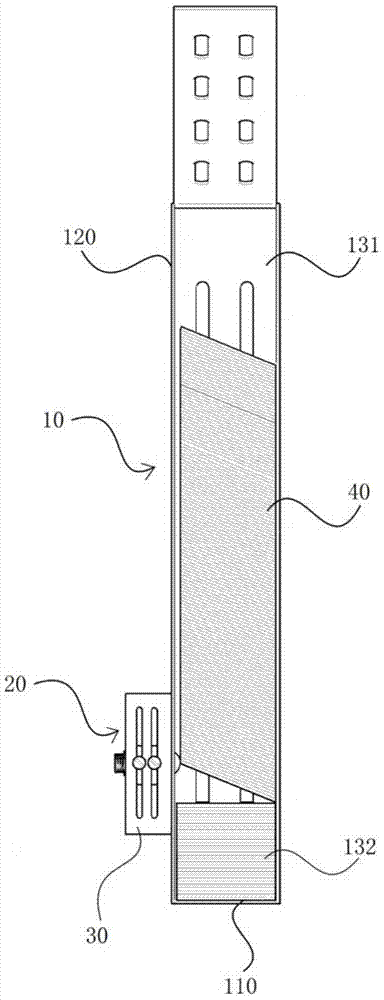
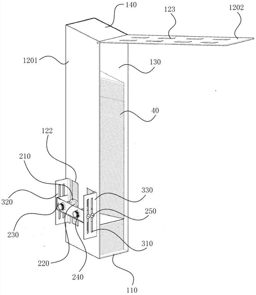
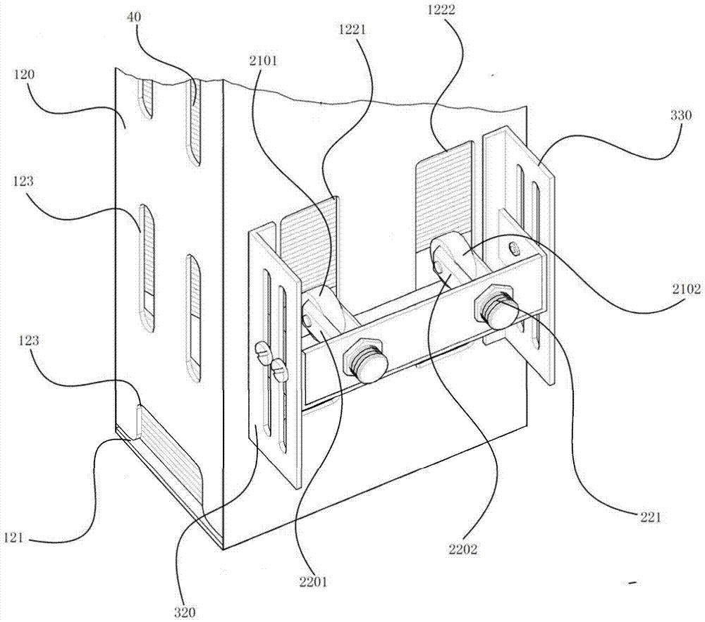
[0032] like Figure 1 to Figure 3 As shown, a card storage box includes a box body 10 and a roller mechanism 20. The box body 10 is provided with an accommodating cavity 130. The box body 10 is provided with a card outlet 121 and a through hole 122 communicating with the accommodating cavity 130. The through hole 122 is located at Above the bayonet outlet 121, the roller mechanism 20 includes a roller 210, a connector 220, and a fixed seat 230 fixed on the outer periphery of the casing 10. One end of the connector 220 is fixedly connected to the fixed seat 230, and the other end is movably connected to the roller 210. 210 passes through the through hole 122 and extends into the receiving cavity 130 , the cards 40 above the rollers 210 are stacked horizontally and obliquely, and the cards 40 below the rollers 210 are stacked horizontally.

[0033]The card stor...


PUM


Abstract

The invention relates to a card hopper, an automatic card sender and a method for increasing the card storing capacitor of an automatic card sender. The card hopper comprises a box and a roller mechanism, wherein the box is provided with an accommodating cavity; a card outlet which is communicated with the accommodating cavity and a through hole are formed in the box; the through hole is positioned above the card outlet; the roller mechanism comprises a roller, a connecting piece and a fixed seat which is fixed on the periphery of a side board; one end of the connecting piece is fixedly connected with the fixed seat, and the other end of the connecting piece is movably connected with the roller; the roller passes through the through hole, and extends into the accommodating cavity; cards positioned above the roller are overlapped horizontally and obliquely; the cards below the roller are overlapped horizontally. A part of the gravity of upper cards is carried by the roller, so that the total weight of the cards is reduced, transferred and dispersed, the friction resistance on a contact surface of bottommost cards in the card hopper is lowered, the card storing capacity of the card hopper is increased, the cards can be pulled out normally, the normal running of a parking lot can be ensured, and the consumption of labor force is lowered.

Description

technical field [0001] The invention relates to the technical field of automatic card issuing machines, in particular to a card storage box, an automatic card issuing machine and a method for increasing the card storage capacity of the automatic card issuing machine. Background technique [0002] At present, public parking lots and community parking lots basically adopt an intelligent management mode. The entrance of the intelligent parking lot is unattended, and the automatic card issuing machine at the entrance ticket box automatically issues the card, which greatly improves the operating efficiency of the parking lot. However, the existing automatic card issuing machines rely on the driving motor to automatically send out the cards at the bottom. Since the upper card will exert a certain pressure on the bottom card, and the rated load of the driving motor is limited, the general design capacity of the card storage box of the existing automatic card issuing machine is about...

Claims


Application Information

Patent Timeline
Patent Type & Authority Patents(China)
IPC IPC(8): G06K13/14G06K13/10
Inventor 何楚湘李奕富
Owner GUANGDONG ANJUBAO INTELLIGENT CONTROL SYST
Why Eureka
Try Eureka