Patient transfer bed for medical treatment

A transfer bed and medical technology, applied in the field of medical patient transfer beds, can solve the problems of complex transmission mechanism and rigid support mechanism, long friction rollers, occupying more space in the width direction, etc., so as to avoid secondary damage and reduce Friction, simple structure effect

Inactive Publication Date: 2015-05-27
JIANGSU DEFENG MEDICAL EQUIP
View PDF6 Cites 5 Cited by
  • Summary
  • Abstract
  • Description
  • Claims
  • Application Information

AI Technical Summary

Problems solved by technology

The synchronous structure of the conveying cloth of this electric transfer bed is complicated, and the volume is large, because the synchronous mechanism of the friction roller is used, the friction roller is indispensable, and the friction roller will occupy more space in the width direction
The friction roller is long, the transmission mechanism and the rigid suppo

Method used


Image

  • Patient transfer bed for medical treatment
  • Patient transfer bed for medical treatment

Examples


Embodiment Construction

[0029] The technical scheme of the present invention will be further explained below in conjunction with the drawings.

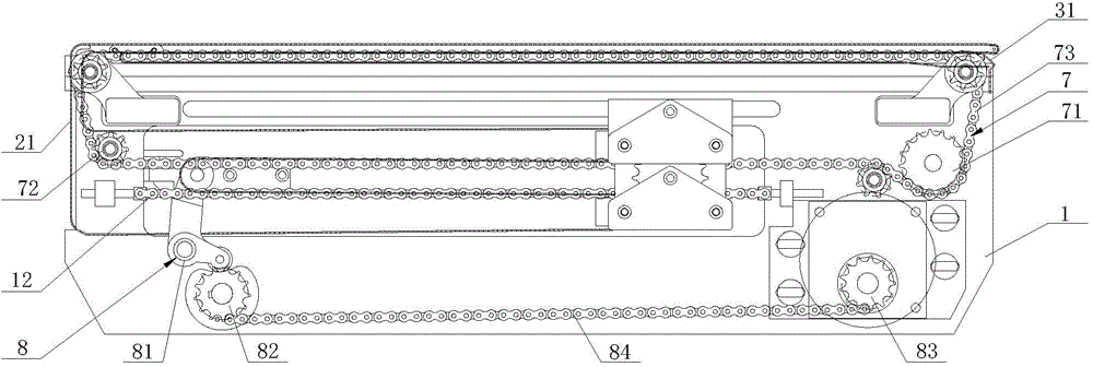
[0030] See figure 1 , figure 2 As shown, a medical patient transfer bed includes a bed frame 1, a sliding bed plate slidably mounted on the bed frame 1, a driving device mounted on the lower part of the bed frame 1, and a roller assembly mounted on the lower part of the bed frame 1. The driving device drives the sliding bed board to move out and return inward along one side of the bed frame 1.

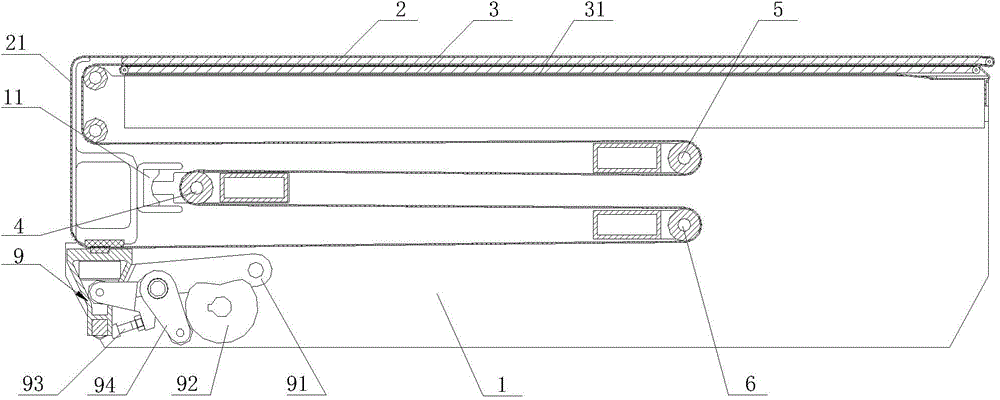
[0031] See figure 2 As shown, the sliding bed plate includes a lower sliding plate 3 and an upper sliding plate 2 mounted on the bed frame from bottom to top. The roller assembly at least includes a fixed roller 4 fixed on the side away from the moving end of the sliding bed plate and located at the fixed The upper sliding roller 5 and the lower roller 6 on the upper and lower sides of the roller shaft 4, the upper sliding roller 5 and the lower roller 6 move synchro...


PUM


Abstract

The invention discloses a patient transfer bed for medical treatment. The patient transfer bed comprises a bedstead, a sliding bed plate, a driving device and a roll shaft assembly, wherein the sliding bed plate is mounted on the bedstead, the driving device is mounted at the lower part of the bedstead, and the roll shaft assembly is mounted on the bedstead; the sliding bed plate comprises a lower sliding plate and an upper sliding plate which are sequentially mounted on the bedstead from bottom to top, and the roll shaft assembly at least comprises a fixed roll shaft, which is fixedly arranged at one side far away from a moving-out end of the sliding bed plate, and two sliding roll shafts which are located at the upper and lower sides of the fixed roll shaft and can synchronously move along the width direction of the bedstead. The transfer bed further comprises an upper conveying cloth belt, a lower conveying cloth belt, a first brake mechanism and a second brake mechanism, wherein the upper conveying cloth belt wraps the peripheral outer side of the upper sliding plate and the peripheral outer side of the roll shaft assembly, the lower conveying cloth belt wraps the peripheral outer side of the lower sliding plate, and the first brake mechanism and the second brake mechanism are mounted on the bedstead. The transfer bed has the advantages that the structure is simple, the operation is convenient, a body of a patient cannot be subjected to manual intervention during the transferring of the patient, and secondary injury to the patient is avoided.

Description

technical field [0001] The invention relates to a medical device, in particular to a medical patient transfer bed. [0002] Background technique [0003] In the field of medical care, bedridden patients are often encountered, such as transferring bedridden patients from the ward to the operating room or from the operating room to the ward, especially for comatose, seriously injured and paralyzed patients. At present, the traditional method of transportation is manual transportation, which will bring about a large change in the patient's position during the transportation process. Not only is the labor intensity of the medical staff high, but it may also cause secondary injuries to the patient and cause unnecessary pain for the patient. And now the more advanced electric patient transfer bed has been put into use. Its principle is to use electric telescopic plates to realize the action of picking up and sending patients, and the synchronous movement of the conveying cloth is...

Claims


Application Information

Patent Timeline
IPC IPC(8): A61G1/00A61G1/04
Inventor 范义东陈钢沈磊蔡渊源姚东
Owner JIANGSU DEFENG MEDICAL EQUIP
Why Eureka
Try Eureka