

Synchronous track device
A synchronous, orbital technology, used in bearings, linear motion bearings, shafts and bearings, etc., can solve the problems of cage overtravel, uncoordinated, serious accidents, etc., achieve long service life of parts, reduce energy loss, The effect of saving lubricating oil
Inactive Publication Date: 2015-05-27
李雪娇
View PDF0 Cites 0 Cited by
- Summary
- Abstract
- Description
- Claims
- Application Information
AI Technical Summary
Problems solved by technology
[0002] The existing roller cross guide rail pair is composed of two V-shaped guide rails, roller cages, cylindrical rollers, etc., which perform reciprocating motion. When the equipment is subjected to inertia in one direction or installed vertically, due to the inertia Or the effect of gravity, it is easy to slip and run, resulting in the asynchrony of the guide rails (uncoordinated pace), which may cause the over-travel phenomenon of the cage, resulting in interference between the limit baffle of the cross guide rail and the cage, which is easy to affect its cross guide rail pair. Normal stress operation, or even damage to the cage, serious accidents may occur
Method used
View moreImage
Smart ImageViewing Examples

Examples
Embodiment 1
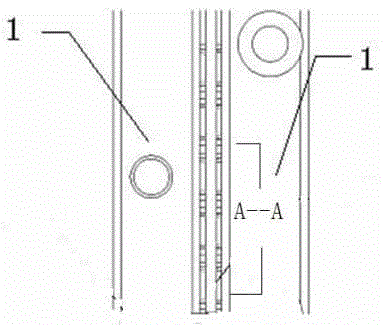
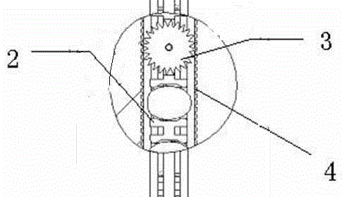
[0013] This embodiment provides a synchronous track device, which is characterized in that: the synchronous track device includes a track 1, a synchronous wheel 2, a sawtooth 3, and a gear 4;
[0014] Wherein: the track 1 is provided with a sawtooth 3 at the contact surface with the synchronous wheel 2, and the synchronous wheel 2 is provided with a gear 4 meshing with the sawtooth 3.
[0015] Described gear 4 is one, is arranged on the middle part of synchronous wheel 2.
Login to View More PUM
 Abstract
A synchronous track device is characterized in that the synchronous track device comprises a track, a synchronizing wheel, sawtooth and a gear, wherein the sawtooth is arranged on the track where the track and the synchronizing wheel are contacted; the gear which is engaged with the sawtooth is arranged in a retainer; and there is one gear which is arranged in the middle part of the synchronizing wheel. According to the synchronous track device, the retainer is synchronous with the cross-track at any time, and the retainer will not be damaged. Thus, service life of cross guide pairs is prolonged.
Description
technical field [0001] The invention relates to a reciprocating roller cross guide rail pair, in particular to the field of a roller cross guide rail pair device with absolutely synchronous cages, and particularly provides a synchronous track device. Background technique [0002] The existing roller cross guide rail pair is composed of two V-shaped guide rails, roller cages, cylindrical rollers, etc., which perform reciprocating motion. When the equipment is subjected to inertia in one direction or installed vertically, due to the inertia Or the effect of gravity, it is easy to slip and run, resulting in the asynchrony of the guide rails (uncoordinated pace), which may cause the over-travel phenomenon of the cage, resulting in interference between the limit baffle of the cross guide rail and the cage, which is easy to affect its cross guide rail pair. Normal stress operation, or even damage to the cage, serious accidents may occur. Contents of the invention [0003] T...
Claims
Login to View More Application Information
Patent Timeline
 Patent Type & AuthorityApplications(China)
IPC IPC(8): F16C29/04
Inventor李雪娇
Owner李雪娇