Airflow disturbance shield and method

A technology of airflow disturbance and airflow, which is applied to vibration measurement in fluids, affects the airflow flowing through the surface of the aircraft, measures vibration and other directions, and can solve problems affecting the connection of aircraft components, adding aircraft components, and affecting components, etc.

Active Publication Date: 2017-06-23
MESSIER DOWTY
View PDF8 Cites 0 Cited by
  • Summary
  • Abstract
  • Description
  • Claims
  • Application Information

AI Technical Summary

Problems solved by technology

However, the inventors of the present application have discovered that existing noise reduction devices (e.g., fairings) can undesirably increase the overall weight of the aircraft
Moreover, existing noise reduction devices (e.g., fairings) can undesirably add skin to aircraft components (e.g., landing gear and / or high-lift devices) and affect connections between aircraft components
Fairings and the like also affect the cooling of components (eg brake components) and are usually directional meaning ineffective in tailwind conditions

Method used


Image

  • Airflow disturbance shield and method
  • Airflow disturbance shield and method
  • Airflow disturbance shield and method

Examples


Embodiment Construction

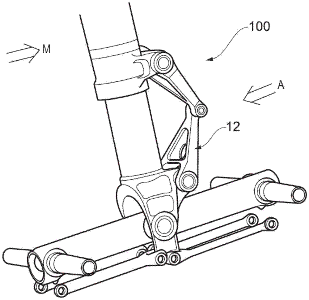
[0047] Figure 1 shows a prior art landing gear 100 . The landing gear 100 includes a noise inducing area 12 represented in the form of a hinge of twisted links. It is conceivable that the landing gear 100 includes a number of noise inducing components and regions suitable for takeoff and landing, for example, the landing gear 100 is shown in the open position.

[0048] Due to the movement of the aircraft to which the landing gear 100 is attached, the landing gear 100 generally moves in the direction of arrow M, which is referred to as the direction of motion M of the landing gear. Accordingly, the airflow moves in the direction of arrow A relative to the landing gear 100 , and this airflow is referred to as airflow A. Airflow A may be considered to be the primary or synthetic airflow from the forward and vertical velocity of the aircraft, which usually also includes a crosswind component.

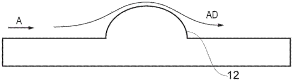
[0049] refer to figure 2 , which schematically shows the noise-inducing component 12...


PUM


Abstract

An airflow disturbance shield (14) for reducing aerodynamic noise generated by an aircraft. The airflow disturbance shield has a base body (14a) and a plurality of airflow disturbance components (14b).

Description

Background technique [0001] Aircraft (eg, airplanes) can generate very loud noises during a landing approach (ie, approaching landing). Much of this noise is produced by air flowing around the open landing gear and / or high lift devices (eg, flaps and slats). [0002] Although during the landing sequence, the aircraft travels at a speed of about 80m / s, the airflow around the noise-inducing components or the area of ​​the aircraft frame and landing gear can reach a speed of about 300m / s, which produces a noise of about 200W Form dissipated sound energy. The noise may be tonal, eg whistle noise due to air flow over the cavity, low frequency rumble from the wing box, or broadband noise, ie noise over a wide range of frequencies. The turbulent airflow around the aircraft and the noise of the wake is very loud, and the airflow around the aircraft (especially around the wings) can cause components of the landing gear and high-lift devices to vibrate, which in turn can cause other c...

Claims


Application Information

Patent Timeline
Patent Type & Authority Patents(China)
IPC IPC(8): B64C21/10B64C23/06B64C25/00
CPCB64C2230/14B64C21/10B64C23/06B64C2025/003Y02T50/10B64C23/00B64C25/00B64C1/40G01H3/00
Inventor 斯图尔特·莱西杰夫·卡姆勒皮特·迈克利兹
Owner MESSIER DOWTY
Why Eureka
Try Eureka