Printing relief block

A technology for printing letterpress and printing area, which is applied in printing, printing machines, rotary printing machines, etc., and can solve problems such as inability to spread alignment liquid, poor corner display, and affecting display quality

Inactive Publication Date: 2015-06-03
BOE TECH GRP CO LTD +1
View PDF5 Cites 4 Cited by
  • Summary
  • Abstract
  • Description
  • Claims
  • Application Information

AI Technical Summary

Problems solved by technology

[0006] The purpose of the present invention is to provide a printing letterpress to overcome the fact that the printing effective area pattern in the printing letterpress of the prior art is a rectangle, causing the alignment liquid to be easily blocked by the metal c

Method used


Image

  • Printing relief block
  • Printing relief block
  • Printing relief block

Examples


Embodiment 1

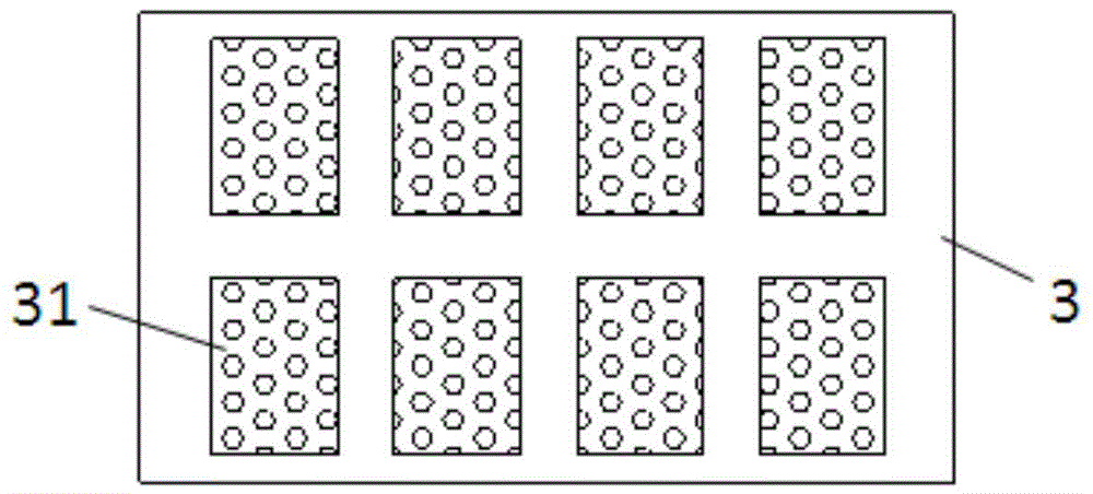
[0028] Such as Figure 5 As shown, the present invention provides a printing relief, which includes: a plurality of effective printing areas 32 are arranged on the printing relief, an ineffective printing area is arranged between the two adjacent effective printing areas, and in the effective printing area The pattern of the printed body is quadrilateral, and the four vertices of the quadrilateral printed body have protrusions extending outward;

[0029] Several protrusion units are distributed on the printing body and the protrusions. Wherein, the protrusion in this embodiment is in the shape of a semicircle, and the radius of the semicircle is preferably 0.5 mm to 20 mm.

[0030] If the radius of the semicircle is too small, the protruding position is easily blocked by the metal circuit, and the effect of diffusing the alignment liquid cannot be achieved; if the radius of the semicircle is too large, the area of ​​the effective printing area will be exceeded, resulting in a...

Embodiment 2

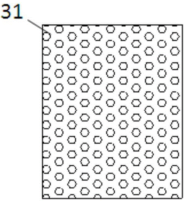
[0033] Such as Image 6 As shown, the difference between this embodiment and Embodiment 1 is that the pattern of the printed body in the effective printing area 33 is a quadrangle, and the four vertices of the quadrangular printed body have protrusions extending outward; the protrusions in this embodiment It is quadrilateral, wherein the side length of the protrusions ranges from 0.1 mm to 20 mm.

[0034] If the side length of the protrusion is too small, the position of the protrusion is easily blocked by the metal circuit, and the effect of diffusing the alignment liquid cannot be achieved; if the side length of the protrusion is too large, the area of ​​the effective printing area will be exceeded, resulting in a waste of printing alignment liquid.

[0035] In this embodiment, quadrilateral protrusions extending outward are added to the four vertices of the quadrilateral printing body. Since the quadrilateral protrusions extending outward are far from the effective display ...

Embodiment 3

[0037] Such as Figure 7 As shown, the difference between the embodiment of the present invention and embodiment 1 is that the printing body in the effective printing area 34 is a quadrangle, and the four sides of the quadrangle are arcs protruding toward the inside of the quadrangle, and the protrusions are arc-shaped, wherein, The radius of the arc is 2 mm to 100 m, and the radius of the arc is 0.5 mm to 20 mm.

[0038] In this embodiment, the printing body adopts a quadrilateral with a specific shape, and arc-shaped protrusions extending outward are added on the four corners. Since the arc-shaped protrusions extending outward are far from the effective display area, they can play a role in diffusing the alignment liquid. Function, it can effectively avoid defects caused by the corner position not being printed due to the blockage of the metal circuit, and ensure the display quality of the effective display area to the greatest extent.

[0039] The printing relief provided ...


PUM

PropertyMeasurementUnit
Radiusaaaaaaaaaa
Side lengthaaaaaaaaaa
Radiusaaaaaaaaaa

Abstract

The invention relates to the technical field of display, in particular to a printing relief block. The printing relief block comprises a plurality of valid printing areas which are arranged on the printing relief block, wherein an invalid printing area is arranged between every two adjacent valid printing areas; a pattern of a printing body in each valid printing area is quadrangular; a bump which extends outwards is arranged at each of the four top corners of the quadrangular printing body; a plurality of bump units are uniformly distributed on the printing body and bumps. According to the printing relief block provided by the invention, the bump which extends outwards is additionally arranged at each of the four top corners of the quadrangular printing body of an effective display area, an orienting material can be uniformly printed on a glass substrate, the phenomenon that poor corner displaying is caused due to the fact that an oriented film is baffled at a corner position by a metal circuit and cannot be diffused is avoided, and display quality is improved.

Description

technical field [0001] The invention relates to the field of display technology, in particular to a printing letterpress. Background technique [0002] Printing letterpress can be used for all kinds of printing, and it is also widely used in the production process of liquid crystal display. Its main function is to print the alignment material (PI) on the glass substrate by using the letterpress printing method when printing the alignment film in the process of producing the liquid crystal display, and form an alignment film on the glass substrate, so that the liquid crystal molecules can be arranged according to certain rules. on a glass substrate. refer to figure 1 , the process of printing the alignment material on the glass substrate is as follows: the anilox roll 1 (anilox roll) rotates counterclockwise, the printing roll 2 (printing roll) rotates clockwise, and at the same time drives the printing relief 3 on it to rotate clockwise, and the glass substrate 4 (glass) ...

Claims


Application Information

Patent Timeline
IPC IPC(8): B41F13/10
Inventor 杨发禄张俊瑞
Owner BOE TECH GRP CO LTD
Why Eureka
Try Eureka