
Rigid impeller feeder

An impeller feeder, rigid technology, applied in the direction of conveyors, rotary conveyors, transportation and packaging, etc., can solve the problems affecting the normal operation of the production line, frequent failures, etc., to achieve significant increase in production and efficiency, prolong the service life of equipment, Effect of failure rate reduction

Inactive Publication Date: 2015-06-03
铜陵市精品工具模具有限责任公司
View PDF0 Cites 0 Cited by
  • Summary
  • Abstract
  • Description
  • Claims
  • Application Information

AI Technical Summary

Problems solved by technology

[0003] The present invention is to solve the problem that the main machine of the feeder and the driving device are driven by chains to cause frequent failures and affect the normal operation of the production line.

Method used


Image

  • Rigid impeller feeder

Examples


Embodiment Construction

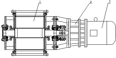
[0009] Such as figure 1 As shown, a rigid impeller feeder of the present invention includes a main machine 1 composed of a frame and an impeller located in the frame and a driving device connected to the main machine 1, and the driving device is fixedly connected with the main machine 1 as a whole. The driving device includes a motor 3 and a speed reducer 2 coupled with the motor 3, and the motor 3 and the speed reducer 2 are fixedly connected as one.


PUM


Abstract

The invention discloses a rigid impeller feeder. The rigid impeller feeder comprises a main engine (1) composed of a rack and an impeller located in the rack and a driving device connected with the main engine (1) and is characterized in that the driving device and the main engine (1) are fixedly connected into a whole. The rigid impeller feeder overcomes and removes inherent shortage of manufacturing of an original feeder, is compact and reasonable in feeder transmission structure, and has the good performance and the reliable structure; the failure rate is obviously reduced, and meanwhile, the feeder fully displays that equipment maintenance and repairing workloads are greatly reduced; the feeder perfectness ratio is improved, and also the production benefits are increased along with the improvement of the perfectness ratio; and the service life of the feeder is obviously prolonged.

Description

technical field [0001] The invention relates to a feeder, especially the connection between a feeder host and a driving device. Background technique [0002] Rigid impeller feeder equipment is widely used in the propulsion and transportation of powdery particles in the chemical industry. The main engine and power mechanism of the old rigid impeller feeder are generally divided into two structures, and the power transmission is realized through the chain. After the equipment runs for a period of time, the chain is elongated and the accelerated sprocket wear occurs. At this time, the center distance between the two sprockets must be adjusted in time, and the bearings are eccentrically worn. The two-body structure is not only huge and complicated to install, but also difficult to maintain, repair and adjust; the original design of the bearings at both ends of the impeller shaft of the rigid impeller feeder uses radial ball bearings. Due to the poor working condition of the eq...

Claims


Application Information

Patent Timeline
Patent Type & Authority Applications(China)
IPC IPC(8): B65G29/00
CPCB65G29/00
Inventor 程路平
Owner 铜陵市精品工具模具有限责任公司
Learn More