
A synchronous swing door device and working method of an automatic mahjong machine

A technology for swing doors and mahjong machines, applied in sports accessories, indoor games, etc., can solve the problems of complex swing door structures and difficulty in keeping the slider speed exactly the same.

Active Publication Date: 2016-06-29
MATSUOTA MECHANICAL & ELECTRICAL CHINA CO LTD
View PDF5 Cites 0 Cited by
  • Summary
  • Abstract
  • Description
  • Claims
  • Application Information

AI Technical Summary

Problems solved by technology

[0003] Among them, the two movable windows of the existing swing door structure device are respectively driven by two motors, and its circuit can only control the two motors to rotate and stop together. The speed of the block is also difficult to keep completely consistent, which is related to factors such as transmission parts, friction coefficient, and the motor itself. The swing door device in the existing fully automatic mahjong machine is prone to the fact that the movable window on one side is closed in place, and the other side is closed. The movable window is not yet in place; in addition, the existing casement door structure is relatively complicated and the control is simple; in view of this, how to design a compact structure, fully automatic casement door structure, and can control the two movable windows to reach the closed position at the same time Technology becomes a technical problem to be solved

Method used


Image

  • A synchronous swing door device and working method of an automatic mahjong machine
  • A synchronous swing door device and working method of an automatic mahjong machine
  • A synchronous swing door device and working method of an automatic mahjong machine

Examples


Embodiment Construction

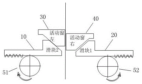
[0040] figure 1 It is a schematic diagram of the structure of the existing automatic mahjong machine swing door movement. It can be seen from the figure that when the swing door is closed, because the motor speed on both sides and the friction force of the sliders on both sides are inconsistent, the sliders on both sides are not synchronous when closing, thus As a result, when the movable window rises, the fast side is high and the slow side is low, which affects the appearance.

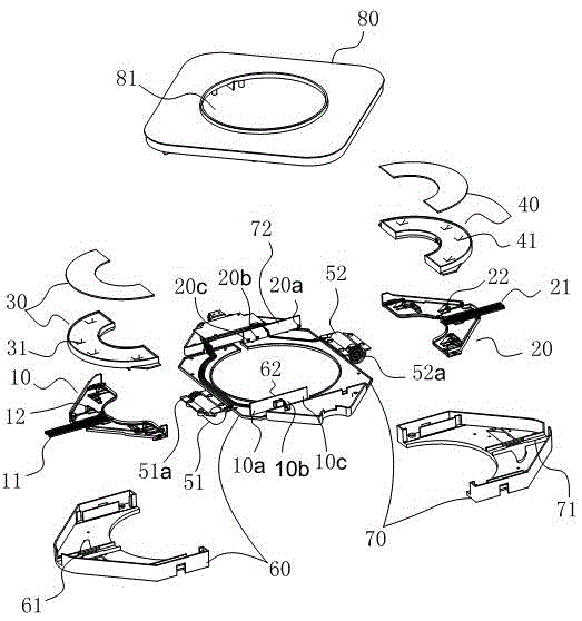
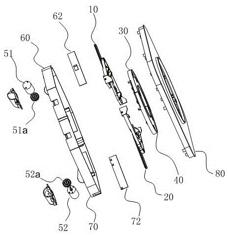
[0041] attached Figure 2-9 It is the accompanying drawing of the embodiment of the present invention, and the embodiment of the present invention will be further described now.

[0042] The present invention adopts the following technical scheme: a synchronous side-opening door device for an automatic mahjong machine, comprising: a left slider 10 and a right slider 20, a left movable window 30 connected to the left slider 10, a left movable window connected to the right slider 20 The right movable...


PUM


Abstract

The invention relates to a synchronous vertical hinged door device of an automatic Majiong machine and a working method. The synchronous vertical hinged door device comprises a left sliding block, a right sliding block, a left movable window connected onto the left sliding block, a right movable window connected onto the right sliding block, a left forward and reverse rotation motor, a right forward and reverse rotation motor, a left induction switch and a right induction switch. The left induction switch, the left forward and reverse rotation motor, the right induction switch and the right forward and reverse rotation motor are all connected into a synchronous vertical hinged door control circuit. According to the synchronous vertical hinged door device, the situation that position sensors are arranged at set positions of closing positions is achieved through the two sliding blocks, the synchronous vertical hinged door control circuit is used for controlling the corresponding motors through software so as to enable the sliding block which arrives at the corresponding set position firstly to wait for the other sliding block which arrives at the other set position later, after the two sliding blocks arrive at the set positions, the two sliding blocks are closed towards the closing positions, and due to the fact that the distances between the two set positions and the closing positions are equal, and the closing synchronization of the movable windows connected with the sliding blocks is greatly improved.

Description

technical field [0001] The invention relates to the technical field of automatic mahjong machines, in particular to a synchronous swing door device and working method of an automatic mahjong machine. Background technique [0002] The automatic mahjong machine is equipped with a shuffling device, a lifting device, a stacking and pushing device, and a swing door device. [0003] Among them, the two movable windows of the existing swing door structure device are respectively driven by two motors, and its circuit can only control the two motors to rotate and stop together. The speed of the block is also difficult to keep completely consistent, which is related to factors such as transmission parts, friction coefficient, and the motor itself. The swing door device in the existing fully automatic mahjong machine is prone to the fact that the movable window on one side is closed in place, and the other side is closed. The movable window is not yet in place; in addition, the existi...

Claims


Application Information

Patent Timeline
Patent Type & Authority Patents(China)
IPC IPC(8): A63F9/20
Inventor 阳琳
Owner MATSUOTA MECHANICAL & ELECTRICAL CHINA CO LTD
Learn More