
Single-drive synchronous unfolding mechanism provided with multiple folding control planes

A technology of unfolding mechanism and folding rudder, which is applied in the field of aerospace, can solve the problems that cannot satisfy the envelope space of storage and transportation and launching devices, it is difficult to guarantee the deployment control and synchronization, and the radial size of missiles is large, so as to ensure flight stability performance, increase the rudder surface extension, and reduce the impact

Active Publication Date: 2015-06-03
ZHEJIANG SCI-TECH UNIV
View PDF6 Cites 27 Cited by
  • Summary
  • Abstract
  • Description
  • Claims
  • Application Information

AI Technical Summary

Problems solved by technology

[0003] The diameter of the traditional small box / barrel missile body is small, and it is generally required to have multiple control rudder surfaces at the same time, and each rudder surface is independently driven by a torsion spring, and its deployment control and synchronization are difficult to guarantee.
At the same time, when the rudder surface has a large extension, the deployment mechanism used makes the radial size of the missile larger when folded, which cannot meet the requirements of the envelope space for storage and transportation and launch devices.

Method used


Image

  • Single-drive synchronous unfolding mechanism provided with multiple folding control planes
  • Single-drive synchronous unfolding mechanism provided with multiple folding control planes
  • Single-drive synchronous unfolding mechanism provided with multiple folding control planes

Examples


Embodiment Construction

[0026] The present invention will be further described below in conjunction with the accompanying drawings and embodiments.

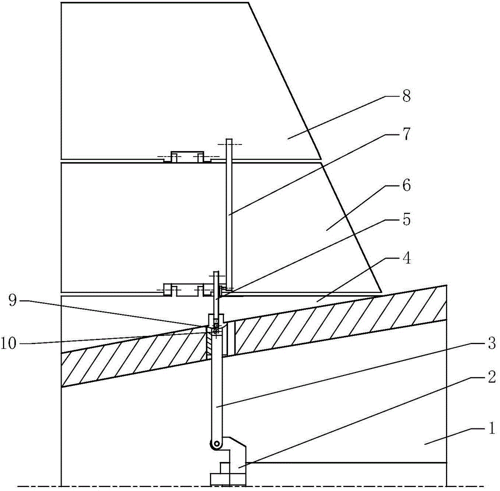
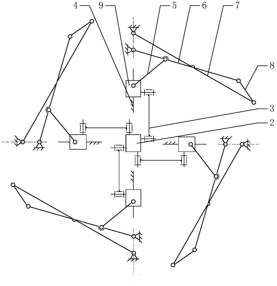
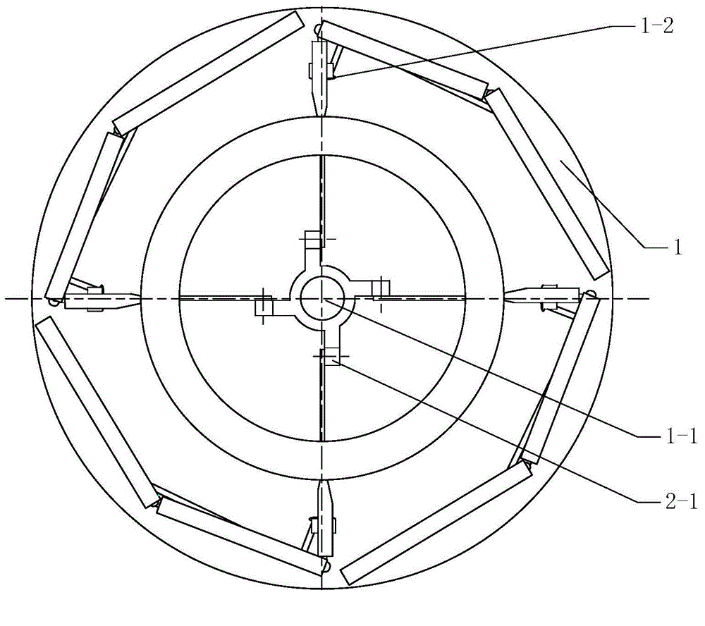
[0027] Such as figure 1 , 2 , 3 and 4, a single-drive multi-folding rudder surface synchronous deployment mechanism includes a cabin body 1, an actuator 2, a connecting rod 3 and four deployment mechanisms; the cabin body 1 is a hollow truncated cone, and the side walls There are four expansion mechanism installation holes 1-2 uniformly distributed along the circumferential direction; the actuator mounting seat 1-1 is fixed at the axis of the cabin body 1; the actuator 2 and the actuator mounting seat 1-1 pass through the sliding pair connection; the actuator 2 is evenly distributed along the circumference with four actuator lugs 2-1, and each actuator lug 2-1 is hinged with the inner end of a connecting rod 3; the outer ends of the four connecting rods 3 Respectively protrude from a deployment mechanism installation hole 1-2, and are hinged with a sl...


PUM


Abstract

The invention discloses a single-drive synchronous unfolding mechanism provided with multiple folding control planes. Each control plane of a traditional small guided missile is independently driven by a torsion spring to be unfolded, synchronism is difficultly ensured, and the adopted unfolding mechanism enable the radial size of the guided missile to be large during folding. The single-drive synchronous unfolding mechanism comprises a cabin body, an actuator cylinder, a connecting rod and four unfolding mechanisms, wherein an actuator cylinder installing seat is fixed to the cabin, the actuator cylinder is connected with an actuator cylinder installing seat sliding pair, four actuator cylinder convex lugs are evenly distributed on the actuator cylinder, each actuator cylinder convex lug is hinged to the inner end of one connecting rod, and the outer ends of the four connecting rods extend out of installing holes formed in the unfolding mechanism respectively and are hinged to slide blocks of the corresponding unfolding mechanism. The unfolding mechanism comprises a rudder stick, the slide blocks, lug pieces, a middle rudder, a rudder tip, connecting rods and a spring locking mechanism, wherein the spring locking mechanism is used for locking the slide blocks and a rudder shaft. The transverse size of a missile body is effectively decreased during control plane folding. The controllability and synchronism in the unfolding process of the four control planes are ensured through driving of the single actuator cylinder.

Description

technical field [0001] The invention belongs to the technical field of aerospace and relates to a missile folding rudder surface unfolding mechanism, in particular to a single-drive multi-folding rudder surface synchronous unfolding mechanism. Background technique [0002] As an aerodynamic wing surface that provides aerodynamic control torque for the missile, the rudder surface is an important part of the missile body. In order to meet the requirements of modern box / barrel launch, folding rudder surfaces need to be widely used. The function of the folding rudder surface unfolding mechanism is to make the rudder surface fold before launch, and automatically unfold and lock reliably under the action of driving force after launch. [0003] The diameter of the traditional small box / barrel missile body is small, and it is generally required to have multiple control surfaces at the same time, and each rudder surface is independently driven by a torsion spring, so it is difficult...

Claims


Application Information

Patent Timeline
Patent Type & Authority Applications(China)
IPC IPC(8): F42B10/14
Inventor 李文娟胡明田芳菲陈文华张阳
Owner ZHEJIANG SCI-TECH UNIV
Learn More