Radiating structure of display module

A technology of heat dissipation structure and display module, which is applied to the structural parts of electrical equipment, cooling/ventilation/heating transformation, optics, etc., can solve the problem of poor heat dissipation and cannot display module heat dissipation, etc. The effect of ensuring cleanliness

Inactive Publication Date: 2015-06-03
KEEWIN DISPLAY CO LTD
View PDF8 Cites 11 Cited by
  • Summary
  • Abstract
  • Description
  • Claims
  • Application Information

AI Technical Summary

Benefits of technology

The technical feature described by this inventor relates to improving cooling efficiency for electronic devices such as LCD displays without affecting their performance or causing damage from external factors like dirt or debris that may be introduced during manufacturing processes. This results in improved quality control over these components while maintaining high-quality image presentation on viewers' screens.

Problems solved by technology

This patented describes different types of display modules that have certain features like lamps or LED lights (Light Emitting Diodes). These display elements require specific functions from their own circuitry called electronic circuits within them. To save money, they often contain these electronics themselves without being able to perform any other tasks during assembly. Additionally, some conventional methods involve adding extra parts at the manufacturing process, leading to increased production time and expenses compared to new technologies. Therefore, this patents proposes improvements over current designs based on thermal management systems.

Method used


Image

  • Radiating structure of display module
  • Radiating structure of display module
  • Radiating structure of display module

Examples


Embodiment Construction

[0023] The present invention will be further described below in conjunction with the accompanying drawings and specific embodiments.

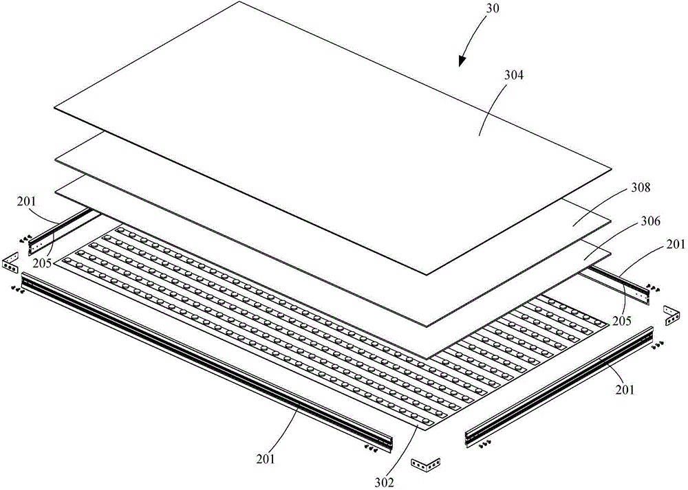
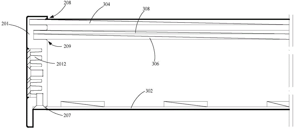
[0024] The invention provides a heat dissipation structure of a display module, which adopts a method of setting ventilation channels to form air convection to dissipate heat from the display module, thereby ensuring the display effect and rapidly dissipating heat from the display module. The existing heat conduction heat dissipation has better heat dissipation effect. The present invention forms a ventilation channel by opening an air inlet and an air outlet on the outer frame, overcomes the existing technical prejudice that the air-cooled heat dissipation cannot be applied to the liquid crystal display module, and ensures that the air inside the display module is clean. Air-cooled air convection dissipates heat from the display module. The heat dissipation structure of the display module of the present invention will be described below with ...


PUM


Abstract

The invention relates to a radiating structure of a display module. The display module comprises an outer frame, and a liquid crystal panel, an optical film, a diffuser plate and a lamp panel which are arranged in the outer frame in sequence, wherein a first module space is formed between the liquid crystal panel and the optical film, the radiating structure comprises an air inlet and an air outlet which are formed on the outer frame, the air inlet and the air outlet form a first ventilation channel in the first module space, and filter screens are arranged at the air inlet and the air outlet. Since the air inlet and the air outlet are formed on the outer frame, the ventilation channel is formed in the first module space between the liquid crystal panel and the diffuser plate, cross-ventilation is formed by ventilation to radiate the display module so that rapid heat dissipating effect is achieved, moreover, since the filter screens are arranged in the ventilation channel, the cleanness in the module space is effectively guaranteed, and thus a good display effect is guaranteed and the influence of dust, granules and the like is avoided.

Description


Claims


Application Information

Patent Timeline
Owner KEEWIN DISPLAY CO LTD
Why Eureka
Try Eureka