Supercharge Your Innovation With Domain-Expert AI Agents!

Synchronous rectifier controller

A synchronous rectification and controller technology, applied in the direction of DC power input conversion to DC power output, AC power input conversion to DC power output, high-efficiency power electronic conversion, etc., to achieve the effect of improving efficiency

Active Publication Date: 2015-06-03
NXP BV
View PDF10 Cites 7 Cited by
  • Summary
  • Abstract
  • Description
  • Claims
  • Application Information

AI Technical Summary

Problems solved by technology

This problem becomes more severe for low power output applications

Method used


Image

  • Synchronous rectifier controller
  • Synchronous rectifier controller
  • Synchronous rectifier controller

Examples


Embodiment Construction

[0050] Corresponding reference numerals are used in the drawings to indicate like features.

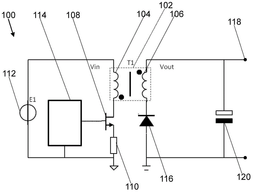
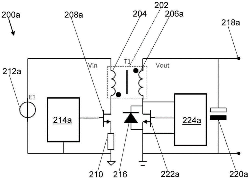
[0051] Figure 2a A flyback converter 200a is shown with a synchronous rectifier on the secondary side. Several features of flyback converter 200a, including: transformer 202 having primary side winding 204 and secondary side winding 206a, switching (primary) transistor 208a, load 210, voltage source 212a, primary side controller 214a, output voltage 218a and smoothing capacitor 220a, similar to figure 1 those characteristics in. Further discussion will for the most part be limited to flyback converter 200a and figure 1 difference between flyback converters.

[0052] The flyback converter 200a includes a synchronous rectification transistor 222a, which may also be referred to as a secondary transistor. The synchronous rectification transistor 222a has a gate, a source and a drain. The source and drain of synchronous rectification transistor 222 a provide a conduction path arrang...


PUM


Abstract

A synchronous rectifier controller (424) for a switched mode power supply (200a; 200b) comprising a transformer (202) with a secondary side winding (206a) and a synchronous rectifier transistor (222a; 222b) with a gate, a source and a drain, the source and drain providing a conduction channel coupled to the secondary side winding (206a), the controller (424) comprising: an input terminal (460) for receiving an input signal (532) related to a voltage at the drain; an output terminal (462) configured to provide an output signal (542) for setting a logic state (467) of the gate; and circuitry (464) having a first threshold (452, 552) and a second threshold (454, 554), the circuitry (464) configured to: generate the output signal (542) in accordance with a comparison between the input signal (632) and the first threshold (452, 552); determine a time period (549) in accordance with the comparison between the input signal (532) and the first threshold (452, 552) and in accordance with a comparison between the input signal (532) and the second threshold (454, 554); and set the first threshold in accordance with the time period (549).

Description

technical field [0001] The present invention relates to switched mode power supplies, such as flyback converters or buck converters including synchronous rectifiers. In particular, but not exclusively, the present invention relates to synchronous rectification controllers for switch mode power supplies. Background technique [0002] Flyback or buck converters are commonly used in power supply units to provide a regulated DC output. figure 1 A flyback converter 100 including a transformer 102 having a primary winding 104 and a secondary winding 106 is shown. Transformer 102 defines a primary side and a secondary side of flyback converter 100 associated with primary winding 104 and secondary winding 106 , respectively. [0003] The primary side of the flyback converter 100 includes a switching transistor 108 having a gate, a source and a drain. Switching transistor 108 may also be referred to as a primary transistor. The source and drain of switching transistor 108 define ...

Claims


Application Information

Patent Timeline
Patent Type & Authority Applications(China)
IPC IPC(8): H02M7/217H02M1/00
CPCH02M1/08H02M3/1588H02M3/33592H02M1/0054Y02B70/10
Inventor 琼·斯特里耶克
Owner NXP BV
Features
  • R&D
  • Intellectual Property
  • Life Sciences
  • Materials
  • Tech Scout
  • Unparalleled Data Quality
  • Higher Quality Content
  • 60% Fewer Hallucinations
Learn More