
Device and method for measuring surface domain soil humidity based on global navigation satellite system-reflection (GNSS-R)

A technology of soil moisture and measuring devices, which is applied in soil material testing, signal transmission systems, instruments, etc., and can solve problems such as not being able to reflect the overall level of soil moisture in the detection area

Active Publication Date: 2015-06-10
山东航向电子科技有限公司
View PDF4 Cites 8 Cited by
  • Summary
  • Abstract
  • Description
  • Claims
  • Application Information

AI Technical Summary

Problems solved by technology

However, since the peak value of the relevant power of the reflected signal only represents the power intensity of the reflected signal in the area near the specular reflection point, that is to say, the obtained soil moisture value can only represent the soil moisture near the reflection point, and cannot reflect the overall level of soil moisture in the entire detection area

Method used


Image

  • Device and method for measuring surface domain soil humidity based on global navigation satellite system-reflection (GNSS-R)
  • Device and method for measuring surface domain soil humidity based on global navigation satellite system-reflection (GNSS-R)
  • Device and method for measuring surface domain soil humidity based on global navigation satellite system-reflection (GNSS-R)

Examples


Embodiment 1

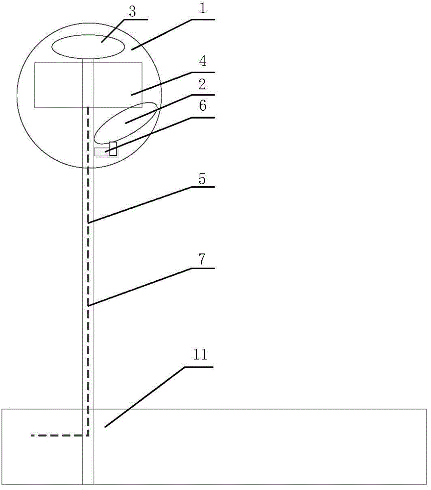
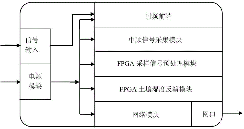
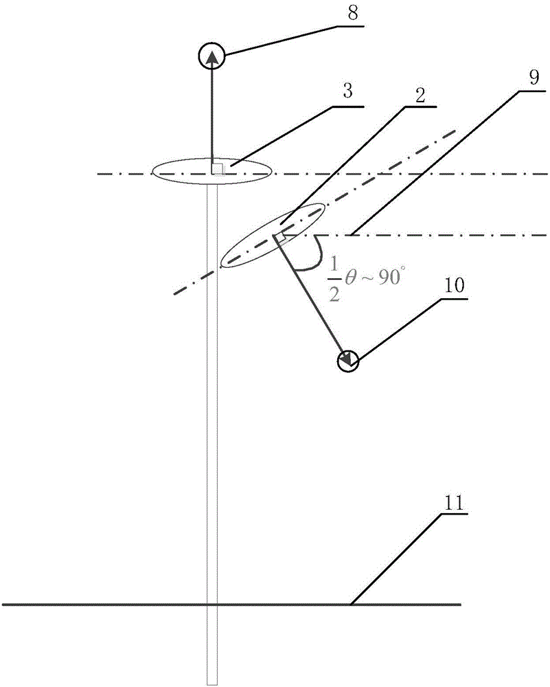
[0058] like Figure 1-2 Shown, the GNSS-R-based area soil moisture measuring device of the present invention includes a chassis 1, a GNSS reflected signal receiving antenna 2, a GNSS direct signal receiving antenna 3 and a GNSS-R soil moisture measuring host 4 are arranged in the chassis 1, and the chassis 1 1 Set an opening facing the ground, one end of the bracket I5 is fixed on the ground, the other end is vertically inserted into the chassis 1 and fixed to the GNSS-R soil moisture measurement host 4, and the top of the GNSS-R soil moisture measurement host 4 is fixed to the GNSS direct signal receiving antenna 3, Bracket II6 is fixed on the bracket I5 between the GNSS-R soil moisture measurement host 4 and the opening of the chassis 1, and the bracket II6 fixes the GNSS reflected signal receiving antenna 2, and the GNSS-R soil moisture measurement host 4 includes the RF front end and intermediate frequency signal connected in sequence The acquisition module, the FPGA sampl...

Embodiment 2

[0062] like Figure 4 As shown, the present embodiment is the measurement method of the GNSS-R-based area soil moisture measuring device described in embodiment 1, comprising the following steps:

[0063] In the first step, the GNSS direct signal and reflected signal are received by the GNSS direct signal receiving antenna and the GNSS reflected signal receiving antenna respectively, and most of the multipath signals that are not related to the transmission path are suppressed;

[0064] In the second step, the RF front-end performs down-conversion on the direct signal and the reflected signal respectively, and obtains two analog intermediate frequency signals corresponding to the direct signal and the reflected signal respectively;

[0065] In the third step, the intermediate frequency signal acquisition module samples and quantifies the two analog intermediate frequency signals to obtain two digital intermediate frequency signals;

[0066] In the fourth step, the two digital...


PUM


Abstract

The invention relates to the technical field of soil humidity measurement, and in particular relates to a device for measuring the surface domain soil humidity based on global navigation satellite system-reflection (GNSS-R). The device comprises a case; the case is internally provided with a GNSS reflected signal receiving antenna, a GNSS direct signal receiving antenna and a GNSS-R soil humidity measurement mainframe; the GNSS-R soil humidity measurement mainframe is fixed by a bracket I; the device is compact in structure and convenient to use, and is capable of integrating signal receiving processing, soil humidity inversion and humidity data transmission. The invention also provides a method for measuring the soil humidity; the method comprises the steps of carrying out partition on the area covered by the GNSS reflected signal receiving antenna according to different code delay by adopting an ICF specific value calculation method; carrying out weighted summation on the related power corresponding to the area according to partition size, then estimating the soil surface reflectivity, and calculating the dielectric constant of the soil to obtain a stable and reliable soil humidity measurement result; finally, transmitting the soil humidity data in real time by a 3G technology to realize real-time observation for the measurement result.

Description

technical field [0001] The invention relates to the technical field of soil moisture measurement, in particular to a GNSS-R-based area soil moisture measurement device and measurement method. Background technique [0002] In the field of soil moisture measurement technology based on GNSS-R, the soil surface reflectance is generally estimated by the correlation power peak ratio of the soil reflection signal and the direct signal, and then the soil dielectric constant is calculated to obtain the soil moisture. However, since the peak value of the relevant power of the reflected signal only represents the power intensity of the reflected signal in the area near the specular reflection point, that is to say, the obtained soil moisture value can only represent the soil moisture near the reflection point, and cannot reflect the overall level of soil moisture in the entire detection area. Contents of the invention [0003] In order to solve the deficiencies in the above-mentioned...

Claims


Application Information

Patent Timeline
Patent Type & Authority Applications(China)
IPC IPC(8): G01N33/24G08C17/02
Inventor 不公告发明人
Owner 山东航向电子科技有限公司
Learn More