
Method for displaying a timing trend and related timepiece

A display method, technology of clocks and watches, applied in the directions of visually indicating time, devices for indicating time, measuring time intervals, etc.

Active Publication Date: 2015-06-10
ETA SA MFG HORLOGERE SUISSE
View PDF8 Cites 2 Cited by
  • Summary
  • Abstract
  • Description
  • Claims
  • Application Information

AI Technical Summary

Problems solved by technology

The multifunction watch thus makes it possible to set and see multiple countdowns to predetermined events simultaneously, however, the multifunction watch is not set up to measure or compare fixed time intervals like a standard chronograph

Method used


Image

  • Method for displaying a timing trend and related timepiece
  • Method for displaying a timing trend and related timepiece
  • Method for displaying a timing trend and related timepiece

Examples


Embodiment Construction

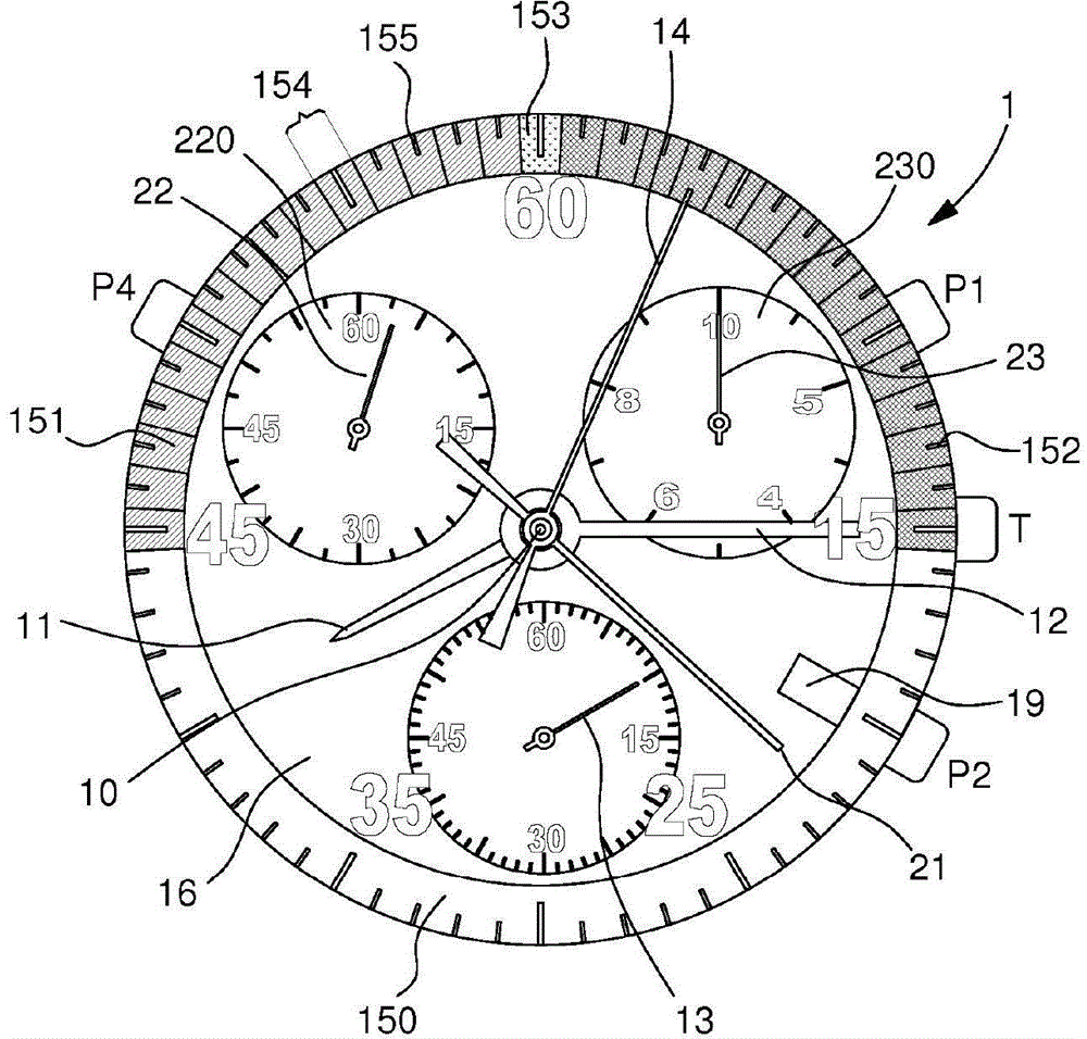
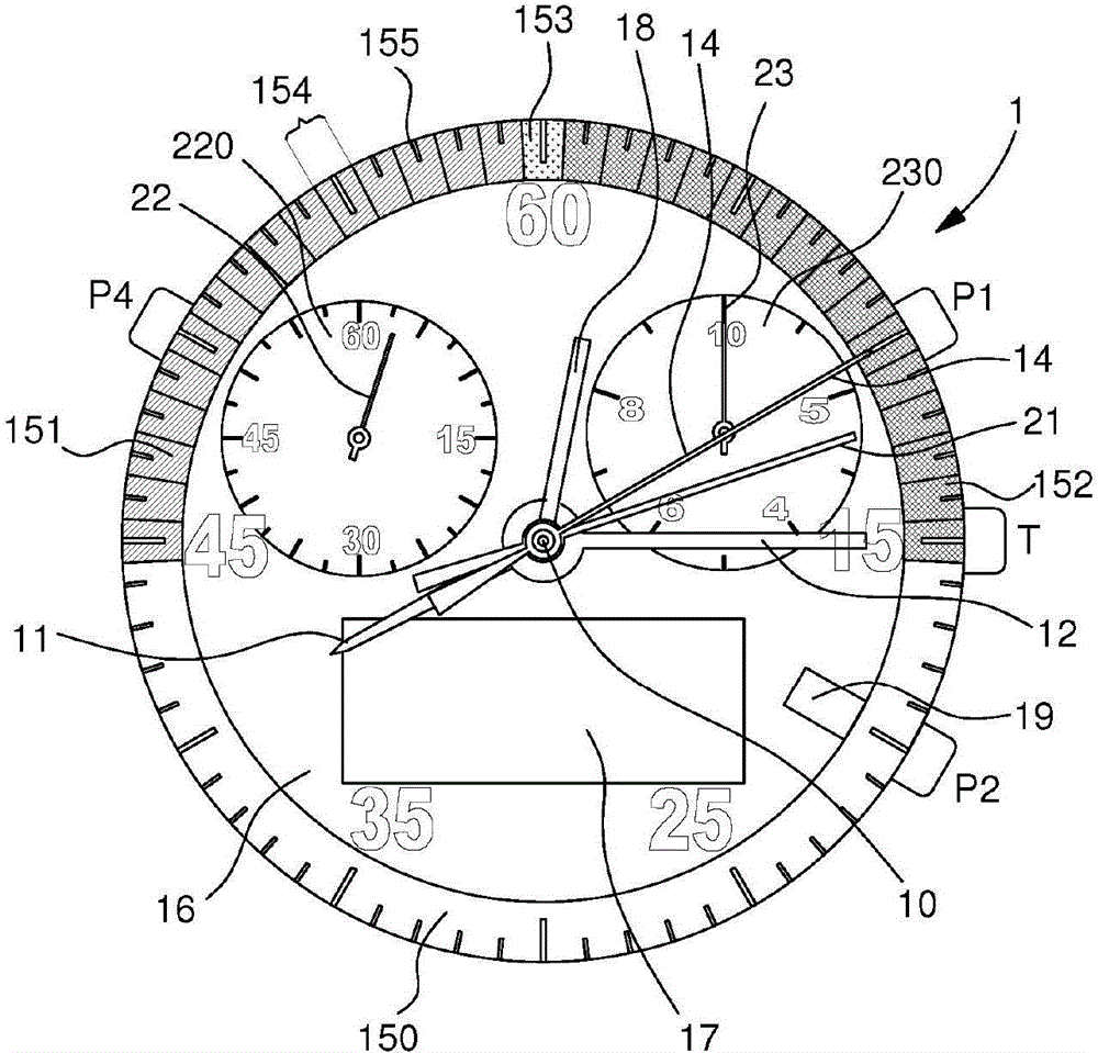
[0015] figure 1 Shown is a wrist watch 1 according to a preferred embodiment of the invention provided with an analog trend indicator 14 consisting of an additional hand turning around a central wheel 10 of hour 11 and minute 12 hands of the movement. The watch 1 comprises a dial 16 on which is mounted a bezel 150 provided on its entire periphery with a series of graduations 155 to facilitate reading the current time and an aperture 19 for the date display at 4 o'clock set on the dial. Furthermore, there are provided three push-buttons P1, P2 and P4 protruding out of the middle part of the case, said push-buttons being used to perform time measuring and setting operations, in particular as referenced below figure 2 Interprets the set of reference intervals used for measurements. There is also a control stem T, which is used to set the current time and to determine the different operating modes. Preferably, the stem is movable axially to at least three different positions, ...


PUM


Abstract

Portable timepiece including an hour hand and a minute hand for the current time display, rotating about a central wheel facing a bezel, and also a chronograph module, wherein the timepiece further includes a first analogue trend indicator relating to a measured time interval.

Description

technical field [0001] The invention relates to a control and display method for a portable time measuring device, more particularly for an electromechanical chronograph. Background technique [0002] Portable electronic chronographs with digital display means have been used for a long time in sporting events to indicate achievements to athletes or their coaches. However, due to the digital nature of the display means, these chronographs do not allow a very intuitive reading of the recorded time, especially in terms of visualizing the difference, since there is no range of movement as in the case, for example, of using hands concept. [0003] Furthermore, chronographs with hands are well known in the field of mechanical timepieces for measuring time intervals, usually with an accuracy of tenths of a second. The long seconds hand is started and then stopped by a pusher, and the measured time interval reads seconds on the bezel and other units of time (eg, minutes, hours or ...

Claims


Application Information

Patent Timeline
Patent Type & Authority Applications(China)
IPC IPC(8): G04F10/00G04B19/04G07C1/24
CPCG04C19/04G04F3/08G04F8/003G04C23/06G04F8/00G04C17/005
Inventor J-B·彼德斯S·莱辰
Owner ETA SA MFG HORLOGERE SUISSE
Learn More