
A phase-changing power socket

A technology of plugging and plugging power supply, which is applied in the direction of circuits, electrical components, and two-component connection devices, which can solve the problems of electrical safety hazards, inconvenience, and large storage space, and achieve aesthetic improvement, easy processing, and reasonable design Effect

Inactive Publication Date: 2018-06-19
郭亚光
View PDF5 Cites 0 Cited by
  • Summary
  • Abstract
  • Description
  • Claims
  • Application Information

AI Technical Summary

Problems solved by technology

[0002] The order of components of the commonly used power strip is: 1. Power cord-2. Switch-3. Jack. The power cord on the switch side of the power strip exposes the strip, which affects the appearance and prevents the power strip Get effective concealment, its practicability, applicability, aesthetics and concealment are greatly affected, and the placement space is large
Since the switch and the power cord are on the same side, it is extremely inconvenient to pull out and push in every time the switch is inserted.
[0003] In addition, the three-phase power supply strip cuts off the power to the electrical appliances through the strip switch. It may happen that the plug strip switch actually disconnects the neutral line, resulting in the electrical appliances still being charged in the power-off state, which makes the electrical appliances have a great safety hazard.
The existing plug-in strips do not have a clear structure that can effectively solve the above problems

Method used


Image

  • A phase-changing power socket
  • A phase-changing power socket

Examples


Embodiment 1

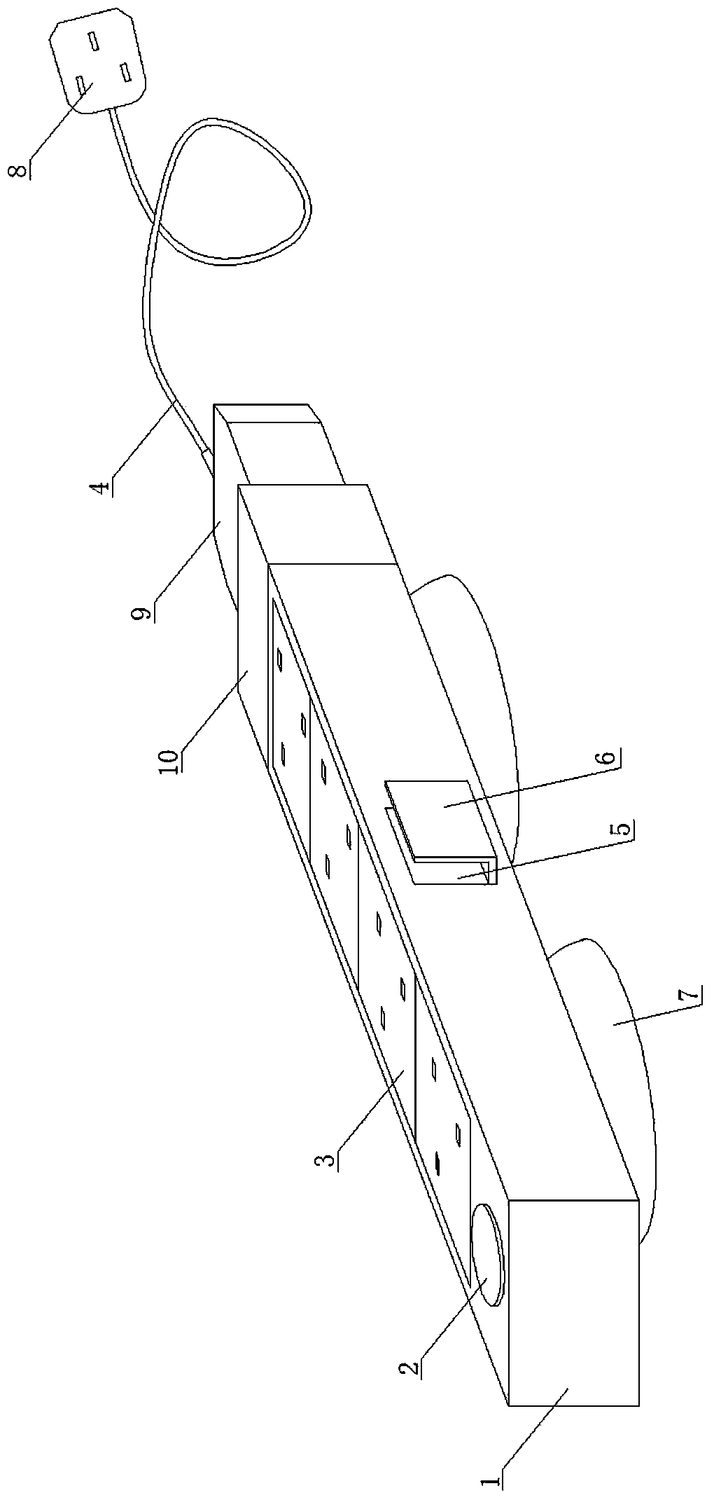
[0016] The phase-changing power supply strip includes a housing 1, a switch 2, a socket area 3 and a power cord 4. A suction cup 7 for positioning is arranged in the middle of the bottom of the housing 1; 5 is provided with a drawable winding button 6; the surface of the other side of the housing 1 opposite to the power cord 4 is provided with a switch 2, and the middle part of the surface of the housing 1 is provided with a jack area 3, and the housing 1 is connected to the power cord 4 One end of the power cord 4 is provided with a reversing socket 10; one end of the power cord 4 is connected to the power plug 8, and the other end of the power cord 4 is connected to the reversing plug 9, and the reversing plug 9 is provided with a live wire hole 15, a grounding hole 16 and a neutral wire hole 17 , the live wire hole 15, the ground hole 16 and the neutral wire hole 17 are on the same horizontal plane, and the distance between the live wire hole 15 and the ground hole 16 is the...

Embodiment 2

[0018] The phase-changing power strip includes a housing 1, a switch 2, a socket area 3 and a power cord 4, and a suction cup 7 for positioning is provided on the front and rear sides of the bottom of the housing 1; a dark groove 5 is provided on the side of the housing 1 , the dark groove 5 is provided with a drawable wire wrap 6; the surface of the other side of the housing 1 opposite to the power cord 4 is provided with a switch 2, and the middle part of the surface of the housing 1 is provided with a jack area 3, and the housing 1 is connected to the One end of the power cord 4 is provided with a phase-changing socket 10; one end of the power cord 4 is connected to a power plug 8, and the other end of the power cord 4 is connected to a phase-changing plug 9, and the phase-changing plug 9 is provided with a live wire hole 15, a grounding hole 16 and a neutral pin. The wire hole 17, the live wire hole 15, the ground hole 16 and the neutral wire hole 17 are on the same horizon...

Embodiment 3

[0020] The phase-changing power supply strip includes a housing 1, a switch 2, a socket area 3 and a power cord 4. Three suction cups 7 for positioning are uniformly arranged on the bottom of the housing 1; 5 is provided with a drawable winding button 6; the surface of the other side of the housing 1 opposite to the power cord 4 is provided with a switch 2, and the middle part of the surface of the housing 1 is provided with a jack area 3, and the housing 1 is connected to the power cord 4 One end of the power cord 4 is provided with a reversing socket 10; one end of the power cord 4 is connected to the power plug 8, and the other end of the power cord 4 is connected to the reversing plug 9, and the reversing plug 9 is provided with a live wire hole 15, a grounding hole 16 and a neutral wire hole 17 , the live wire hole 15, the ground hole 16 and the neutral wire hole 17 are on the same horizontal plane, and the distance between the live wire hole 15 and the ground hole 16 is t...


PUM


Abstract

The invention discloses a phase change power strip and belongs to the field of electrical components. The phase change power strip structurally comprises a shell, a switch, a jack area and a power line. The other surface, in connection with the power line, of the shell is provided with a switch; the center of the surface of the shell is provided with the jack area; one end, in connection with the power line, of the shell is provided with a phase change outlet; one end of the power line is connected with a power plug; the other end of the power plug is connected with a phase change plug; the phase change plug is connected with the phase change outlet by insertion fit. Compared with the prior art, the phase change power strip has the advantages such as reasonable design, simple structure, ease of processing, convenience of use, safety and reliability; concealment and attractiveness are improved; when breakage of a zero wire of the switch leads to an electric appliance being live when powered off, a live wire of the switch can be disconnected by turning the phase change plug at 180 degrees, and thus the electric appliance can be thoroughly powered off.

Description

technical field [0001] The invention relates to the field of electrical components, in particular to a phase-changing power strip. Background technique [0002] The order of components of the commonly used power strip is: 1. Power cord-2. Switch-3. Jack. The power cord on the switch side of the power strip exposes the strip, which affects the appearance and prevents the power strip If it is effectively concealed, its practicability, applicability, aesthetics, and concealment are greatly affected, and the placement space is relatively large. Since the switch and the power cord are on the same side, it is extremely inconvenient to pull out and push in every time the switch is plugged in. [0003] In addition, the three-phase power strip cuts off the power to the electrical appliances through the plug-in switch. It may happen that the plug-in switch actually disconnects the neutral line, resulting in the electrical appliances still being charged in the power-off state, which p...

Claims


Application Information

Patent Timeline
IPC IPC(8): H01R13/70H01R13/46H01R13/72
CPCH01R13/70H01R13/72H01R24/00H01R31/06
Inventor 郭亚光郭小雨
Owner 郭亚光
Learn More