Combination cutter

A truncated, multi-fracture technology, applied in overvoltage arresters, electrical components, spark gaps, etc. using spark gaps, can solve the problems of large discharge counters, less arc extinguishing effect, and re-ignition phenomenon, etc. The effect of protecting safety, improving arc extinguishing performance, and easy extinguishing

Active Publication Date: 2015-06-10
王巨丰 +1
View PDF11 Cites 2 Cited by
  • Summary
  • Abstract
  • Description
  • Claims
  • Application Information

AI Technical Summary

Problems solved by technology

[0011] Although the above patents have played a certain role in arc extinguishing protection for lightning protection, there are still some deficiencies. For example, for multiple lightning, the arc extinguishing effect is not obvious, there is re-ignition phenomenon, etc., and the discharge counter is large in size and difficult to install. In some specific occasions, the anti-interference ability is weak, it is easy to generate wrong counts, the data cannot be stored, manual records are required, and a lot of labor is wasted

Method used


Image

  • Combination cutter
  • Combination cutter
  • Combination cutter

Examples


Embodiment 1

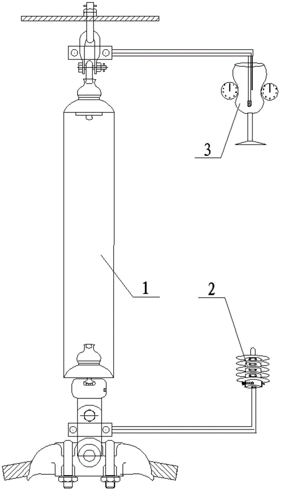
[0046] Such as Figure 1-5 As shown, a combined circuit breaker includes a multi-fracture arc extinguishing device 2 and a horizontal arc extinguishing device 3 fixedly installed at both ends of the insulator 1 through connecting fittings I and connecting fittings II respectively; wherein,

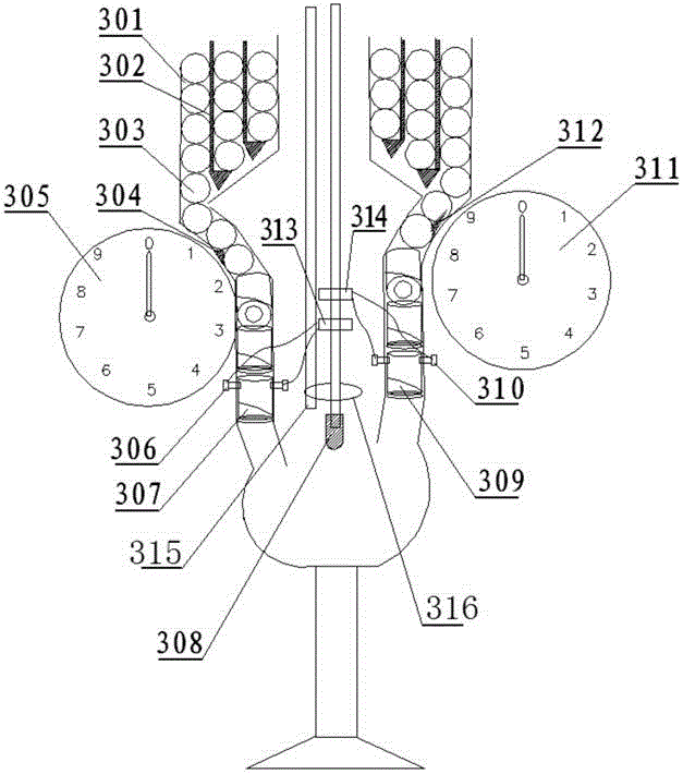
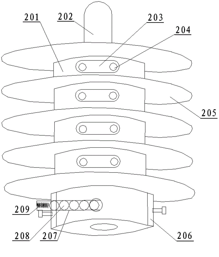
[0047] The multi-fracture arc extinguishing device 2 includes a device main body 201 and an arc starting electrode I 202; the arc starting electrode I 202 is fixedly installed at one end of the device main body 201, and points to the horizontal arc extinguishing device 3, and the other end of the device main body 201 It is fixedly installed at one end of the insulator 1 through the connecting fitting I; the device main body 201 is provided with an arc extinguishing path 204 composed of several sections of arc extinguishing channels 210 and arranged in a Z-shaped cycle; two adjacent arc extinguishing channels 210 is provided with a copper block 203, and each section of the arc extinguishing...

Embodiment 2

[0056] A combined circuit breaker, including a multi-fracture arc extinguishing device 2 and a horizontal arc extinguishing device 3 fixedly installed at both ends of an insulator 1 through connecting fittings I and connecting fittings II; wherein,

[0057] The multi-fracture arc extinguishing device 2 includes a device main body 201 and an arc starting electrode I 202; the arc starting electrode I 202 is fixedly installed at one end of the device main body 201, and points to the horizontal arc extinguishing device 3, and the other end of the device main body 201 It is fixedly installed at one end of the insulator 1 through the connecting fitting I; the device main body 201 is provided with an arc extinguishing path 204 composed of several sections of arc extinguishing channels 210 and arranged in a Z-shaped cycle; two adjacent arc extinguishing channels 210 is provided with a copper block 203, and each section of the arc extinguishing channel 210 is placed with two arc extingu...

Embodiment 3

[0065] A combined circuit breaker, including a multi-fracture arc extinguishing device 2 and a horizontal arc extinguishing device 3 fixedly installed at both ends of an insulator 1 through connecting fittings I and connecting fittings II; wherein,

[0066] The multi-fracture arc extinguishing device 2 includes a device main body 201 and an arc starting electrode I 202; the arc starting electrode I 202 is fixedly installed at one end of the device main body 201, and points to the horizontal arc extinguishing device 3, and the other end of the device main body 201 It is fixedly installed at one end of the insulator 1 through the connecting fitting I; the device main body 201 is provided with an arc extinguishing path 204 composed of several sections of arc extinguishing channels 210 and arranged in a Z-shaped cycle; two adjacent arc extinguishing channels 210 is provided with a copper block 203, and each section of the arc extinguishing channel 210 is placed with two arc extingu...


PUM


Abstract

The invention discloses a combination cutter. The combination cutter comprises an arc extinction device with multiple breaks and a horizontal type arc extinction device, which are fixedly installed at two ends of an insulator respectively through a connection armor clamp I and a connection armor clamp II, wherein an arc extinction route composed of multiple segments of arc extinction channels and arranged in Z-shaped circulation mode is arranged on a main body of the arc extinction device with the multiple breaks, a left side bullet storage bin, a right side bullet storage bin and an arc strike electrode II are arranged in the horizontal type arc extinction device, vertical rails used to transversely place arc extinction gas bullets are arranged in the left side bullet storage bin and the right side bullet storage bin, a preparation rail in a slope shape is arranged at the bottom of each vertical rail, and a gas bullet trigger position is arranged at the tail end of each preparation rail. The combination cutter is simple in structure, reasonable in design, strong in arc extinction ability, stable and reliable in work, capable of counting, and convenient to maintain and replace in a later period.

Description

technical field [0001] The invention relates to a lightning protection device for a power transmission line, in particular to a combined interceptor. Background technique [0002] Lightning is an important factor affecting the safety of transmission lines. It has long occupied the first place in line fault tripping. It is a natural process of atmospheric activity and has not been controlled so far. However, we can analyze the frequent accidents to find the law of lightning strikes and strengthen prevention. For example, towers on high mountains or peaks, transmission lines near ponds or reservoirs, towers crossing mountains or rivers and lakes, and towers installed on high grounding resistance, rocky tower foundations and transmission lines are all vulnerable to lightning damage. focus. [0003] Lightning strikes will bring different forms of damage and damage to power facilities. Thundercloud discharge will cause lightning overvoltage in the power system. Common overvolta...

Claims


Application Information

Patent Timeline
Patent Type & Authority Applications(China)
IPC IPC(8): H01T4/10H01T1/02H01T1/10H01T1/12
Inventor 梁雪吴东李国栋周政刘太东王新阳白鉴知冯凯欧芳志邵攀屹李世荣
Owner 王巨丰
Why Eureka
Try Eureka