
Drive device for automobile engine variable valve lift

A technology of automobile engine and valve lift, applied in the direction of engine components, machines/engines, valve devices, etc., can solve the problems of complex structure, difficult installation of connecting shaft, etc., and achieve the effect of ensuring adjustment

Active Publication Date: 2015-06-17
CHERY AUTOMOBILE CO LTD
View PDF7 Cites 6 Cited by
  • Summary
  • Abstract
  • Description
  • Claims
  • Application Information

AI Technical Summary

Problems solved by technology

The core part of the above-mentioned control mechanism achieves the purpose of adjusting the attitude of the combined rocker arm through the swing of the connecting shaft. The structure is complex, and the installation of the connecting shaft in the engine is relatively difficult.

Method used


Image

  • Drive device for automobile engine variable valve lift
  • Drive device for automobile engine variable valve lift
  • Drive device for automobile engine variable valve lift

Examples


Embodiment Construction

[0013] combined with Figures 1 to 6 , the present invention is described in further detail:

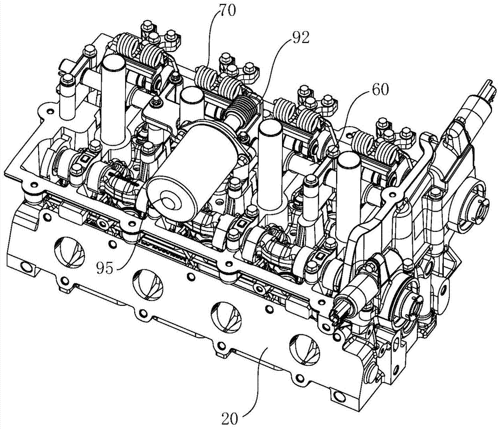
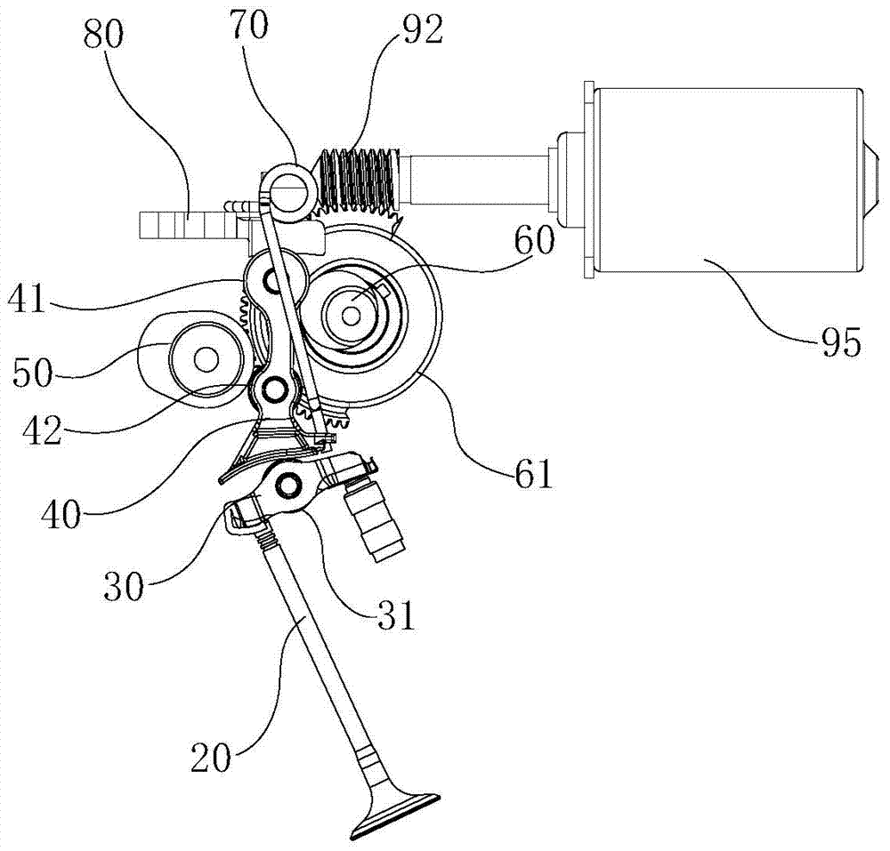
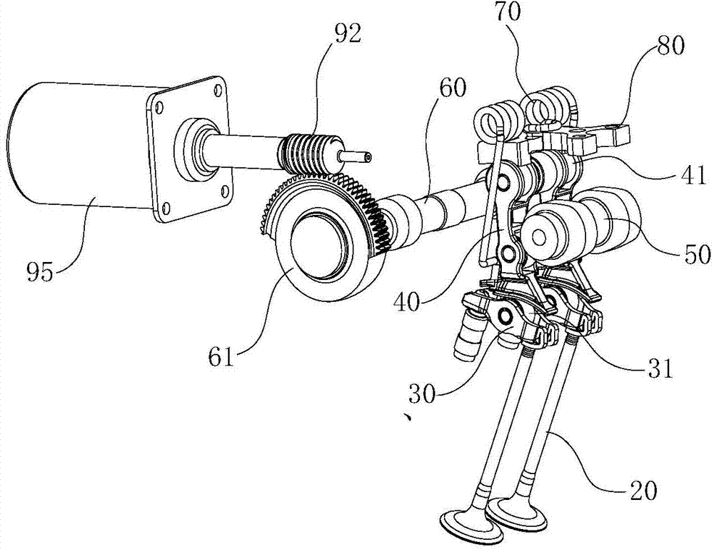
[0014] combine image 3 , a driving device for a variable valve lift of an automobile engine, comprising a valve 20 arranged on the cylinder head 10, one end of the valve rocker arm 30 is connected with the rod end of the valve 20, and the other end of the valve rocker arm 30 is also connected with the valve lifter It is characterized in that: the device also includes an intermediate rocker arm 40, the lower end of the intermediate rocker arm 40 forms a press fit with the middle section of the valve rocker arm 30, the upper end of the intermediate rocker arm 40 abuts against the curved surface of the guide rail of the upper support 80, and the middle The left and right sides of the rocker arm 40 are respectively abutted against the eccentric shaft 60 and the camshaft 50, and the middle rocker arm 40 is also connected with a spring 70, which provides elastic force to drive the middle...


PUM


Abstract

The invention belongs to the technical field of automobile engines, and particularly relates to a drive device for the automobile engine variable valve lift. The drive device comprises a valve arranged on an air cylinder cover, one end of a valve rocker arm is connected with a rod end of the valve, and the other end of the valve rocker arm is further connected with a valve tappet. The device further comprises a middle rocker arm, the lower end of the middle rocker arm is matched with the middle section of the valve rocker arm in an abutting mode, the upper end of the middle rocker arm abuts against a curved guide rail face of an upper support, the left side and the right side of the middle rocker arm abut against an eccentric shaft and a camshaft respectively, the middle rocker arm is further connected with a spring, the spring supplies elastic force so as to drive the middle rocker arm to abut against the camshaft, the swing axis of the middle rocker arm, the axis of the camshaft and the axis of the eccentric shaft are arranged in parallel, the eccentric shaft comprises a rotary shaft and an eccentric wheel arranged on the rotary shaft, a turbine disc is arranged in the middle position of the rotary shaft of the eccentric shaft, the turbine disc and a worm are matched to form a worm wheel and worm mechanism, and a drive mechanism drives the worm to rotate. The opening and closing of the valve and the lift can be adjusted only through the middle rocker arm and the support of four points, and the drive device is simple in structure and high in valve lift adjustment accuracy.

Description

technical field [0001] The invention belongs to the technical field of automobile engines, in particular to a driving device for a variable valve lift of an automobile engine. Background technique [0002] At present, most piston-type automobile engines use the throttling method of the throttle valve to control the air charge entering the engine cylinder. The air charge of the engine's valves, which in turn controls the air charge into the engine's cylinders. However, the mechanical parameters of this type of throttle valve have been set, and when the engine operating conditions are complex, the air charge demand in the cylinder varies greatly with the different engine operating conditions. Taking a gasoline engine as an example, when the load is small, the engine only needs a small air charge, and in order to prevent excess air from entering the cylinder, it is necessary to use the throttle valve to throttle, and the throttling effect of the throttle valve will cause pumpi...

Claims


Application Information

Patent Timeline
Patent Type & Authority Applications(China)
IPC IPC(8): F01L13/00F01L1/18
Inventor 黄国媛沈恩华王孟轲李琼峰段建锋
Owner CHERY AUTOMOBILE CO LTD
Learn More