End face oil configuration for journal bearings

A technology of journal bearings and end faces, which is applied in the field of journal bearings, can solve the problems of increased leakage, etc., and achieve the effect of reducing oil flow rate and reducing emissions

Active Publication Date: 2015-06-17
BORGWARNER INC
View PDF9 Cites 8 Cited by
  • Summary
  • Abstract
  • Description
  • Claims
  • Application Information

AI Technical Summary

Problems solved by technology

However, the increased oil flow at the axially outer surface of the journal bearing would be in close proximity to the piston seals, and thus exactly where leakage is most likely, thereby increasing oil leakage from the bearing housing to the turbocharger opportunities for the turbine section or compressor section

Method used


Image

  • End face oil configuration for journal bearings
  • End face oil configuration for journal bearings
  • End face oil configuration for journal bearings

Examples


no. 1 example

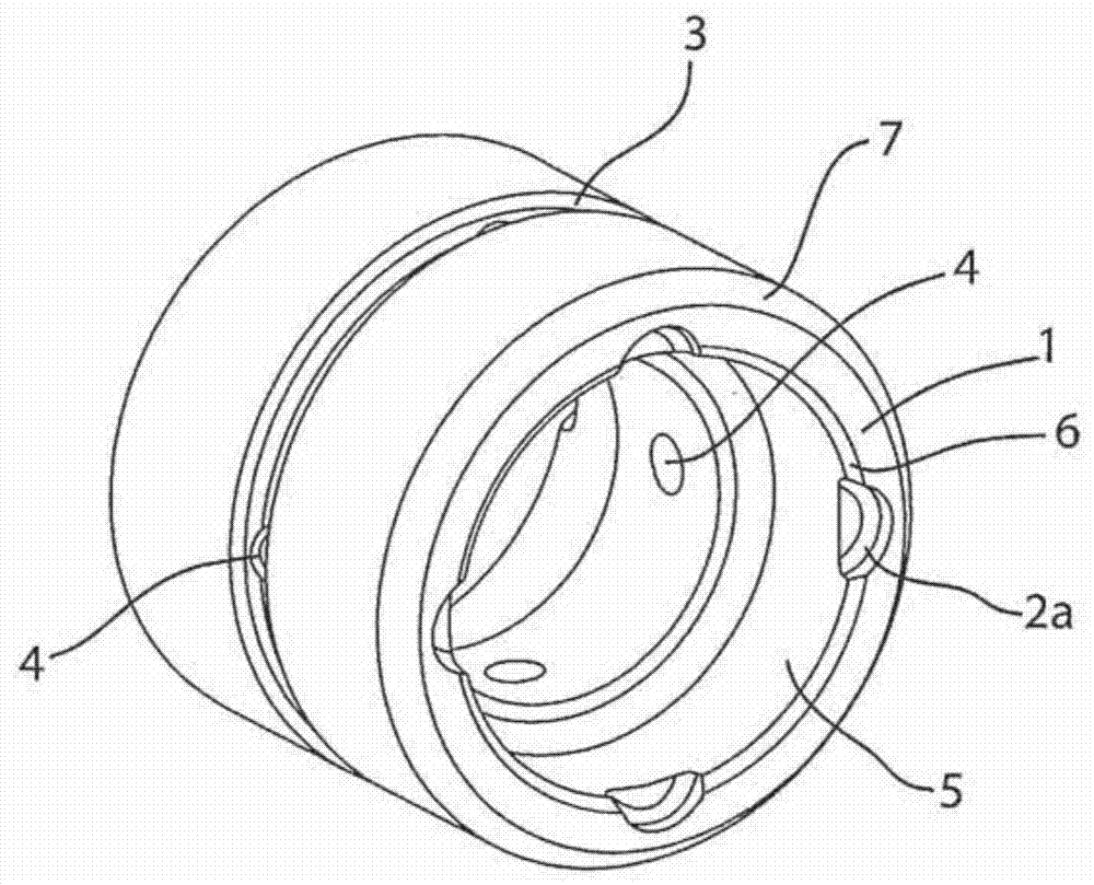
[0018] figure 1 A first embodiment of the inventive journal bearing end face of the present invention is depicted;

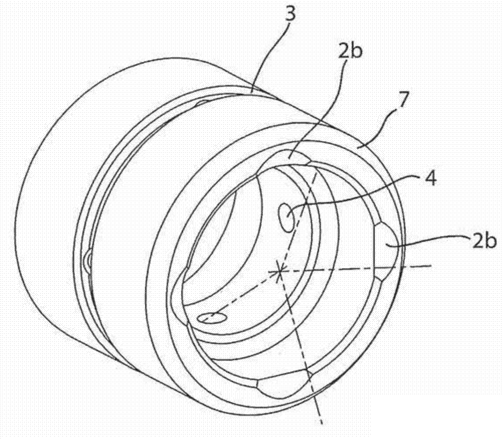
[0019] figure 2 depicts a second embodiment of an end face of a journal bearing of the present invention; and

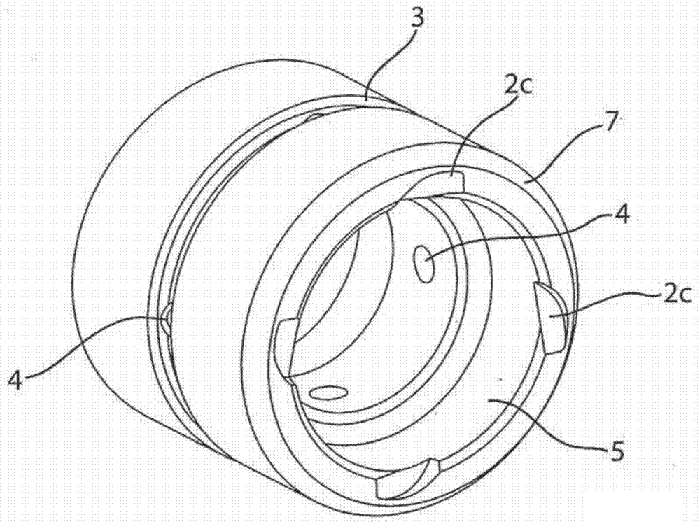
[0020] image 3 A third embodiment of an end face of a journal bearing of the present invention is depicted.

[0021] Detailed Description of the Invention

[0022] A journal bearing with a face according to the invention is improved especially in terms of guaranteeing the oil flow in the case of axial thrust, without requiring modification of the turbocharger except for the replacement of the conventional journal bearings by the inventive journal bearings. Revise. The journal bearing can be a "floating" journal bearing with a three-piece design, where the two journal bearings are separated by a bearing spacer, or it can be a "fixed" journal bearing with a one-piece design or a three-piece design. "Journal bearings. Therefore, the operation of ...


PUM


Abstract

A journal bearing, such as for a turbocharger, having an axial end face designed for improved balance of lubrication and thrust. The journal bearing axial end face is modified so that it provides thrust, yet does not easily allow oil to escape before allowing lubrication to take place between the bearing and the adjacent face.

Description

field of invention [0001] The present invention relates to turbochargers for internal combustion engines and more particularly to a journal bearing having an axial face designed to improve the balance of lubrication and thrust. More specifically, the present invention provides a journal bearing with which oil flow can be reduced and reliably maintained even when the shaft is being subjected to axial loads. Background of the invention [0002] Turbochargers are widely used to increase the performance of internal combustion engines. The hot exhaust gas drives a turbine rotor, which drives a compressor rotor via a turbocharger shaft. In the case of diesel engines, temperatures of approximately 740° C. occur in the exhaust turbine, while in the case of Otto-cycle engines temperatures of above approximately 1,000° C. occur. A car's turbocharger operates at extremely high rotational speeds, sometimes exceeding 200,000RPM. Despite these severe conditions, what is now required ar...

Claims


Application Information

Patent Timeline
Patent Type & Authority Applications(China)
IPC IPC(8): F16C33/10F02B39/00F02B39/14
CPCF16C2360/24F01D25/166F01D25/186F05D2220/40F16C17/047F16C17/10F16C33/106F16C33/1075F16C32/0629
Inventor D·N·沃德
Owner BORGWARNER INC
Why Eureka
Try Eureka