A Piston Compressor with Anti-Shock Function

A compressor and piston technology, which is applied in the field of piston compressors with anti-liquid shock function, can solve the problems that liquid cannot be recovered, there is no anti-liquid shock compressor, etc., and achieve the effect of preventing liquid shock accidents and protecting them from damage

Inactive Publication Date: 2017-02-22
苏州天荣能源环境科技有限公司
View PDF6 Cites 2 Cited by
  • Summary
  • Abstract
  • Description
  • Claims
  • Application Information

AI Technical Summary

Problems solved by technology

At present, compressors with a "false cover" structure can only be used in refrigeration applications, and can only be made into single-acting cylinders, and the released liquid cannot be recovered. It is used in industrial fields (especially industrial heat pumps for chemical unit operations) The compressors in the world are basically double-acting structures, and there is no anti-liquid shock compressor that can be used in the corresponding field.

Method used


Image

  • A Piston Compressor with Anti-Shock Function
  • A Piston Compressor with Anti-Shock Function
  • A Piston Compressor with Anti-Shock Function

Examples


Embodiment 1

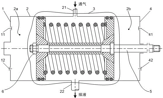
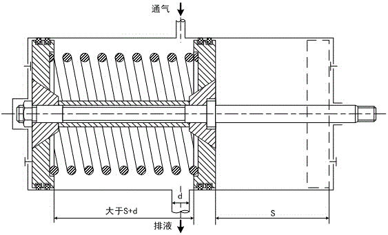
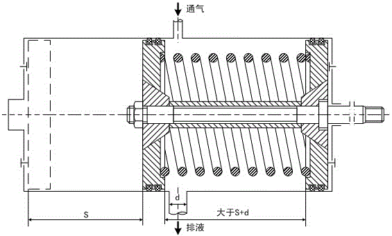
[0032] Such as Figure 1 ~ Figure 3 As shown, the cylinder head part 1, the cylinder body part 2, and the cylinder seat part 4 constitute the cylinder part of the double-acting piston compressor, and the combined piston part 3 with a special structure is coaxially placed in the cylinder part, and the combined piston 3 consists of the first piston A fastening nut 6 is mounted on the end of the piston rod 5, and suction and exhaust valve parts 11, 12, 41, 42 are respectively provided on the cover side and the shaft side of the cylinder part. Such as Figure 4 ~As shown in Figure 8, a movable end plate 32 and 37 are respectively provided at both ends of the combined piston part 3, and the center of the first movable end plate 32 and the second movable end plate 37 is provided with an inner taper hole, which respectively passes through A first locating cone 31 and a second locating cone 38 with an outer tapered surface are installed on the end of the piston rod 5, and the inner t...

Embodiment 2

[0036] Such as Figure 9 As shown, on the basis of Embodiment 1, the small ends of the two positioning cones 31 and 38 of the combined piston 3 each have a small section of cylinder, and the ends of the two small sections of the two cylinders are offset to realize the two movable end plates 32 and 37 axial distance, thereby eliminating the need for image 3 The positioning sleeve 36 in the first embodiment simplifies the structure of the piston part 3 and improves the positioning accuracy.

Embodiment 3

[0038] Such as Figure 10 As shown, on the basis of Embodiment 1, there are two positioning shoulders 5e and 5e1 on the piston rod 5 with different diameters, and the two positioning cones 31 and 38 of the combined piston part 3 respectively abut against the The two positioning shoulders 5e1 and 5e are used for axial positioning, and the outer cylindrical surfaces 5b and 5d of the corresponding shoulders 5e1 and 5e on the piston rod 5 are used for radial positioning, and the first piston is tightly positioned respectively. The fastening nut 6 and the second piston fastening nut 7 are respectively fastened to the fastening thread 5 a and the second fastening thread 5 a 1 on the piston rod 5 to form the combined piston part 3 , thereby omitting the positioning sleeve 36 .


PUM


Abstract

The invention discloses a piston compressor with the liquid impact preventing function. The piston compressor comprises a cylinder cover part, a cylinder body part and a cylinder seat part. The cylinder cover part, the cylinder body part and the cylinder seat part are sequentially connected. A combined piston part is coaxially arranged in the cylinder body part. A first piston fastening nut is arranged at the left end of the combined piston. A piston rod is arranged at the right end of the combined piston. The cylinder cover part is provided with a cover side air suction valve and a cover side exhaust valve, the upper cylinder wall and the lower cylinder wall of the middle of the cylinder body part are provided with a radial cylinder body vent hole and a radial cylinder body drain port respectively, and the cylinder seat part is provided with a shaft side air suction valve and a shaft side exhaust valve. When the compressor is operated, liquid in work cavities can be automatically released, a cylinder is protected against a liquid impact accident, and the compressor is protected against damage. Meanwhile, closed recovery of the released liquid can be achieved, and even though a compressed medium is harmful or dangerous to the environment, the compressed medium cannot be released to the environment.

Description

technical field [0001] The invention relates to a piston compressor, in particular to a piston compressor with the function of preventing liquid shock. Background technique [0002] The piston compressor relies on the reciprocating motion of the piston coaxially arranged in the cylinder to realize the compression and delivery of the gas, and the gas enters and exits the working chamber through the suction and exhaust valves arranged at the end of the cylinder or in the radial direction. The piston compressor is used in industrial production. It has a wide range of uses and a wide range of working conditions in various fields, and is an extremely important industrial equipment. Compared with the cross-sectional area of ​​the cylinder, the co-flow area of ​​the suction and exhaust valves of the piston compressor is relatively small. The structure and working principle of the piston compressor determine that it can only transport gas medium, and cannot work with liquid, especia...

Claims


Application Information

Patent Timeline
Patent Type & Authority Patents(China)
IPC IPC(8): F04B39/12F04B39/10F04B39/00
Inventor 高秀峰冯诗愚邵振宇
Owner 苏州天荣能源环境科技有限公司
Why Eureka
Try Eureka