Power supply control method and system

A technology of power supply system and power supply control, which is applied in the field of air conditioning, can solve the problems of low utilization rate, achieve the effect of solving low utilization rate and improving power generation utilization rate

Active Publication Date: 2015-06-24
GREE ELECTRIC APPLIANCES INC
View PDF5 Cites 3 Cited by
  • Summary
  • Abstract
  • Description
  • Claims
  • Application Information

AI Technical Summary

Problems solved by technology

[0008] Embodiments of the present invention provide a power supply control method and system to at least solve the technical problem of low utilization rate caused by being fixed in one power supply mode in the prior art

Method used


Image

  • Power supply control method and system
  • Power supply control method and system
  • Power supply control method and system

Examples


Embodiment 1

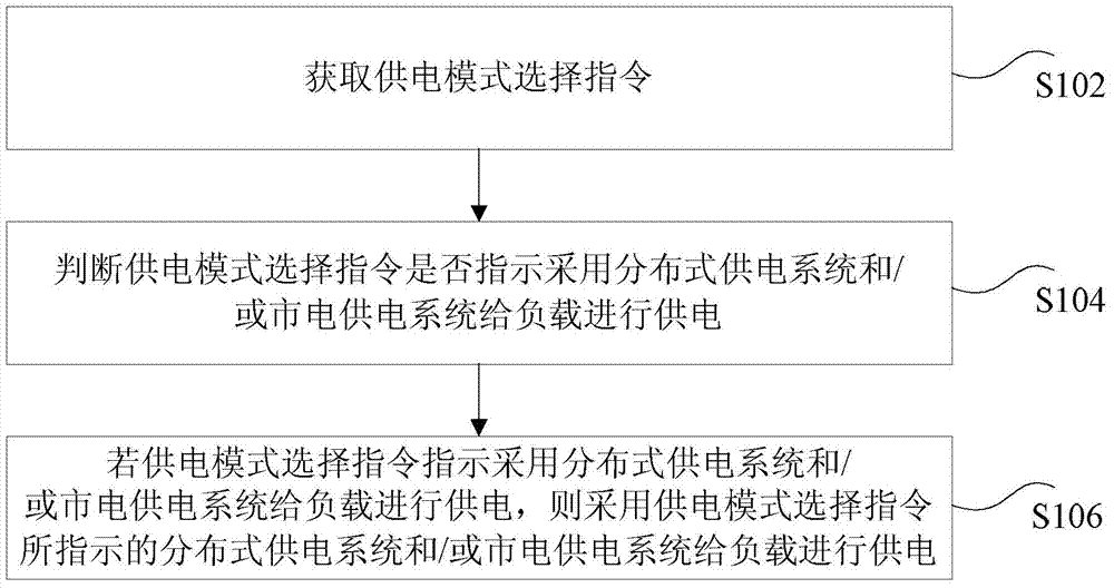
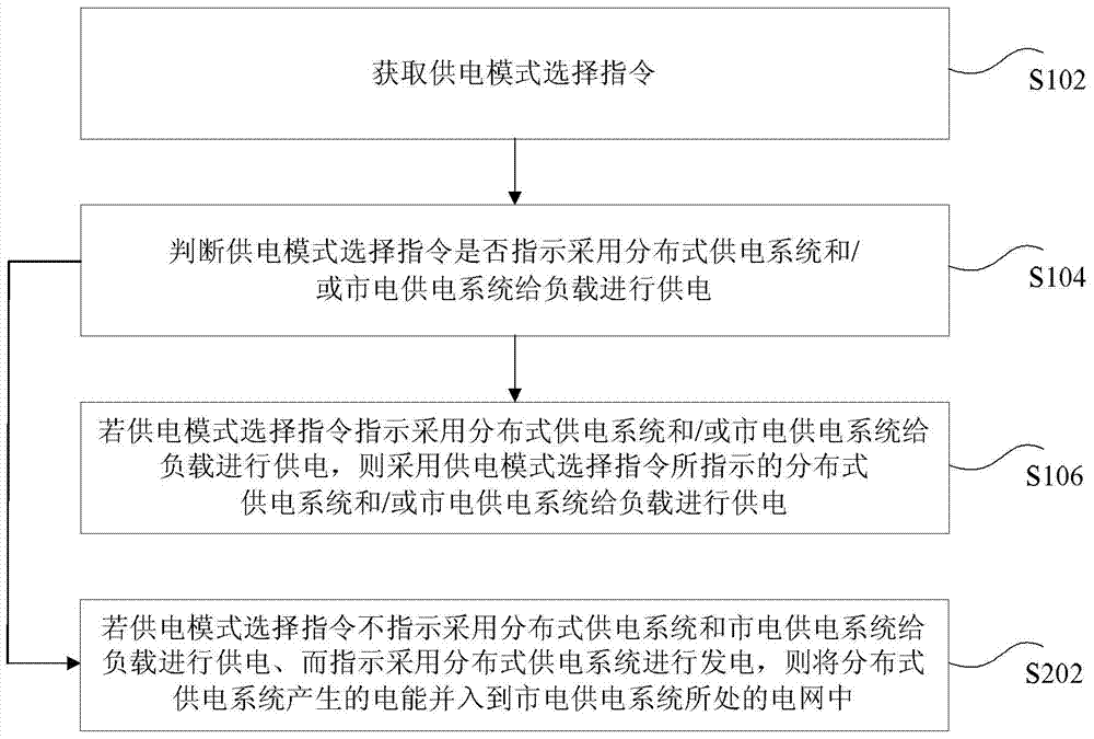
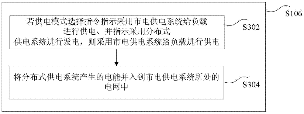
[0041] According to an embodiment of the present invention, a power supply control method is provided, such as figure 1 As shown, the power supply control method in this embodiment includes:

[0042] S102, acquiring a power supply mode selection instruction;

[0043] Optionally, in this embodiment, the above-mentioned power supply mode selection instruction can be received on the power supply management platform, and the above-mentioned power supply management platform can connect and manage multiple loads, for example, a photovoltaic direct-drive air conditioner. The management platform selects different power supply modes according to the above-mentioned power supply mode selection instructions, for example, using photovoltaic direct current to directly drive the air-conditioning unit. Of course, the above example is only an example, and the present application does not limit it.

[0044] Optionally, the load in this embodiment may be, but not limited to, an air conditione...

Embodiment approach

[0068] As an optional implementation, part of the electric energy generated by the distributed power supply system is provided to the load, and the remaining part of the electric energy generated by the distributed power supply system is incorporated into the grid where the mains power supply system is located;

[0069] For example, taking the photovoltaic direct-drive air conditioner as an example, the power supply mode of the above-mentioned air conditioner adopts a two-way power supply mode. First, the electric energy generated by the photovoltaic power supply system is provided to the air conditioner, and the remaining part of the electric energy generated by the photovoltaic power supply system is incorporated into the mains power supply system. in the grid. In this embodiment, the electric energy generated by the photovoltaic power supply system is fully utilized to provide power for the air conditioner and also provide electric energy generated by photovoltaic power gene...

Embodiment 2

[0118] According to an embodiment of the present invention, a power supply control system is also provided, such as Image 6 As shown, the power supply control system in the embodiment of the present invention includes:

[0119] 1) An acquisition unit 602, configured to acquire a power supply mode selection instruction;

[0120] Optionally, in this embodiment, the above-mentioned power supply mode selection instruction can be received on the power supply management platform, and the above-mentioned power supply management platform can connect and manage multiple loads, for example, a photovoltaic direct-drive air conditioner. The management platform selects different power supply modes according to the above-mentioned power supply mode selection instructions, for example, using photovoltaic direct current to directly drive the air-conditioning unit. Of course, the above example is only an example, and the present application does not limit it.

[0121] Optionally, the load i...


PUM


Abstract

The invention discloses a power supply control method and system. The method comprises the steps of acquiring a power supply mode selecting instruction; judging whether the power supply mode selecting instruction indicates that a distributed generation system and/or mains supply system is adopted for providing power for a load; providing power for the load by means of the distributed generation system and/or mains supply system indicated by the power supply mode selecting instruction if yes. The power supply control method and system solve the technical problem of the prior art that utilization rate is low due to the fact that only one power supply mode is available, and achieve the technical effect that load power supply mode can be adjusted as needed so that the utilization rate of power generated by the power supply system can be increased.

Description

technical field [0001] The present invention relates to the field of air conditioners, in particular to a power supply control method and system. Background technique [0002] At present, although the traditional photovoltaic power generation monitoring system and air conditioning group control system have developed quite maturely, there are still the following problems: [0003] (1) The traditional photovoltaic power generation system only provides solutions for photovoltaic power stations. Although the solution is quite mature, it lacks the centralized control and management of electrical equipment, and it does not control the electrical equipment of the HVAC system. . [0004] (2) The traditional HVAC group control system usually adjusts the load of the HVAC system by detecting parameters such as the temperature or pressure difference of the chilled water supply and return main pipe, and basically does not consider changes in the outdoor environment; [0005] (3) The tr...

Claims


Application Information

Patent Timeline
Patent Type & Authority Applications(China)
IPC IPC(8): H02J3/38
Inventor 周获何玉雪姜春苗宋海川
Owner GREE ELECTRIC APPLIANCES INC
Why Eureka
Try Eureka