LED dimming and color adjusting circuit

A circuit and dimming technology, which is applied in the field of LED lighting, can solve the problems of large voltage difference of the step-down drive circuit, difficulty in realizing constant voltage power supply, abnormal operation, etc., and achieve constant voltage, good effect of dimming and color adjustment

Inactive Publication Date: 2015-06-24
ZHONGSHAN SHARPRO LIGHTING TECH CO LTD
View PDF0 Cites 6 Cited by
  • Summary
  • Abstract
  • Description
  • Claims
  • Application Information

AI Technical Summary

Problems solved by technology

However, for the LED power supply module, the boost and buck drive circuits in the power supply module need to sample the voltage of the LED, and then adjust the power supply voltage of the LED. Since the forward voltage VF of the LED is proportional to the current, the LED current is reduced to When it is very small, the VF value of the LED will become very small, which will cause the boost drive circuit to fail to work or cause the voltage difference of the buck drive circuit to be too large to work normally, making it difficult to achieve constant voltage power supply

Method used


Image

  • LED dimming and color adjusting circuit
  • LED dimming and color adjusting circuit
  • LED dimming and color adjusting circuit

Examples


Embodiment Construction

[0026] Below, in conjunction with accompanying drawing and specific embodiment, the present invention is described further:

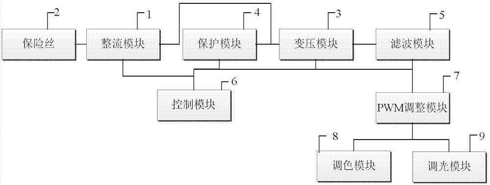
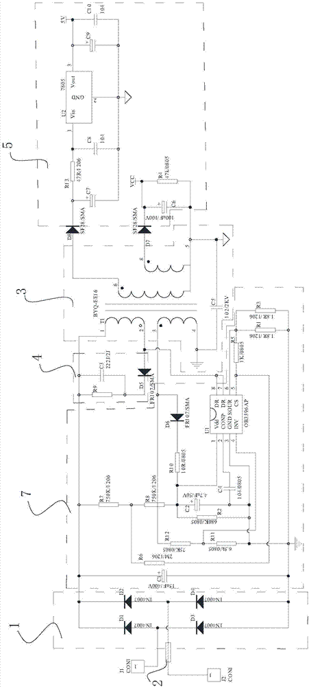
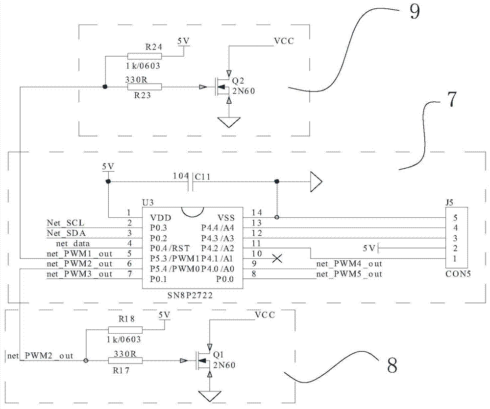
[0027] refer to Figure 1 to Figure 3 , an LED dimming and coloring circuit described in this embodiment, including a rectification module 1, a fuse 2, a transformer module 3, a protection module 4, a filtering module 5, a control module 6, a PWM adjustment module 7, and a coloring module 8 And dimming module 9. The rectification module 1 is used to convert alternating current into direct current. The fuse 2 is connected between the rectifier module 1 and the AC power supply. The transformer module 3 is connected to the output end of the rectifier module 2, and is used for transforming the direct current output by the rectifier module 2, for example, from high voltage to low voltage. The protection module 4 is connected to the input of the transformer module 3 . The protection module 4 is used to protect the color adjustment module 8 and the light a...


PUM


Abstract

The invention discloses an LED dimming and color adjusting circuit. The LED dimming and color adjusting circuit comprises a rectifying module, a fuse, a voltage transformation module, a protecting module, a filter module, a control module, a PWM adjustment module, a color adjusting module and a dimming module. The rectifying module is used for converting an alternating current into a direct current. The fuse is connected between the rectifying module and an alternating-current power source. The voltage transformation module is connected with the output end of the rectifying module and used for transforming the voltage of the direct current output by the rectifying module. The protecting module is connected with the input end of the voltage transformation module. The filtering module is used for filtering the current output by a transformer. The rectifying module, the voltage transformation module and the protecting module are all connected with the control module. The control module is used for controlling the voltage output by the voltage transformation module. The PWM adjusting module is connected with the filtering module and used for generating PWM control signals. The color adjusting module is connected with the PWM adjusting module and is used for adjusting the color of an LED lamp. The dimming module is connected with the PWM adjusting module and is used for adjusting the brightness of the LED lamp. The LED dimming and color adjusting circuit can achieve constant-voltage power supply and has good dimming and color adjusting effects.

Description

technical field [0001] The invention relates to the technical field of LED lights, in particular to an LED dimming and coloring circuit. Background technique [0002] Since the brightness of an LED is almost directly proportional to its driving current, the method of adjusting the forward current of the LED is usually used to adjust the brightness, which is simple and practical. However, for the LED power supply module, the boost and buck drive circuits in the power supply module need to sample the voltage of the LED, and then adjust the power supply voltage of the LED. Since the forward voltage VF of the LED is proportional to the current, the LED current is reduced to When it is very small, the VF value of the LED will become very small, which will cause the boost drive circuit to fail to work or cause the voltage difference of the buck drive circuit to be too large to work normally, making it difficult to achieve constant voltage power supply. Contents of the invent...

Claims


Application Information

Patent Timeline
Patent Type & Authority Applications(China)
IPC IPC(8): H05B37/02
Inventor 徐敏中
Owner ZHONGSHAN SHARPRO LIGHTING TECH CO LTD
Why Eureka
Try Eureka