Electronic ballast based LED lamp tube

A technology of electronic ballasts and LED lamps, which is applied in the layout of electric lamp circuits, electric light sources, lighting devices, etc., can solve the problems of serious pollution of fluorescent lamps and so on.

Active Publication Date: 2015-07-01
GUANGZHOU LEDIA LIGHTING CO LTD
View PDF6 Cites 4 Cited by
  • Summary
  • Abstract
  • Description
  • Claims
  • Application Information

AI Technical Summary

Problems solved by technology

Due to the heavy metal pollutant "mercury", the scrapped fluorescent tubes pollute the environment very seriously

Method used


Image

  • Electronic ballast based LED lamp tube
  • Electronic ballast based LED lamp tube
  • Electronic ballast based LED lamp tube

Examples


Embodiment Construction

[0019] The present invention will be further described below in conjunction with the accompanying drawings of the description.

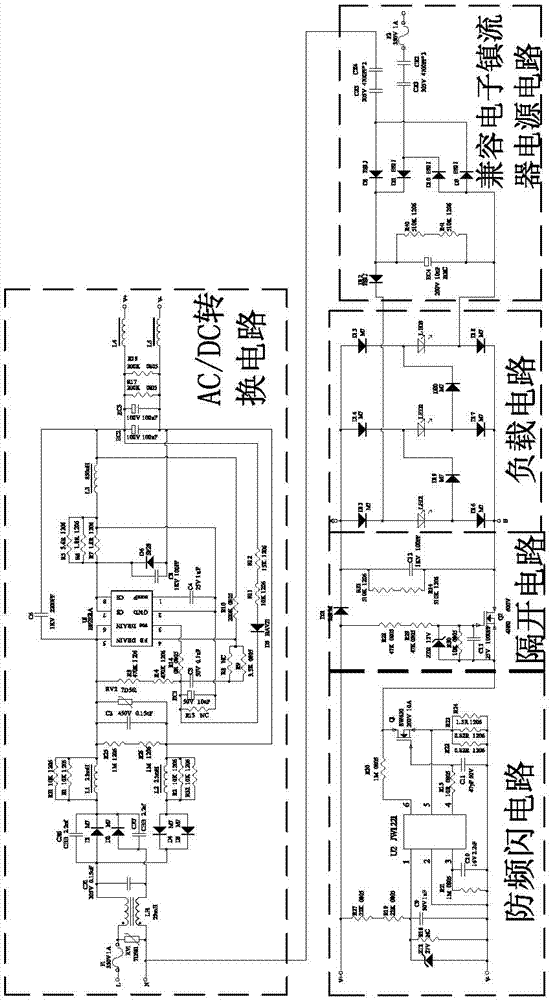
[0020] Such as figure 1 As shown, an LED lamp based on an electronic ballast includes a load circuit, an AC / DC conversion circuit, an anti-flicker circuit, a separation circuit and a compatible electronic ballast power supply circuit; the AC / DC conversion circuit includes The input terminals L1 and N are connected to the input terminal of the anti-flicker circuit, and the compatible electronic ballast power supply circuit includes an input terminal L2, and the other input terminal is connected to the input terminal N of the AC / DC conversion circuit; When the ballast is input, the input terminal L1 and the input terminal N are short-circuited as one input terminal, and the input terminal L2 is used as the other input terminal; It is not connected when it is suspended.

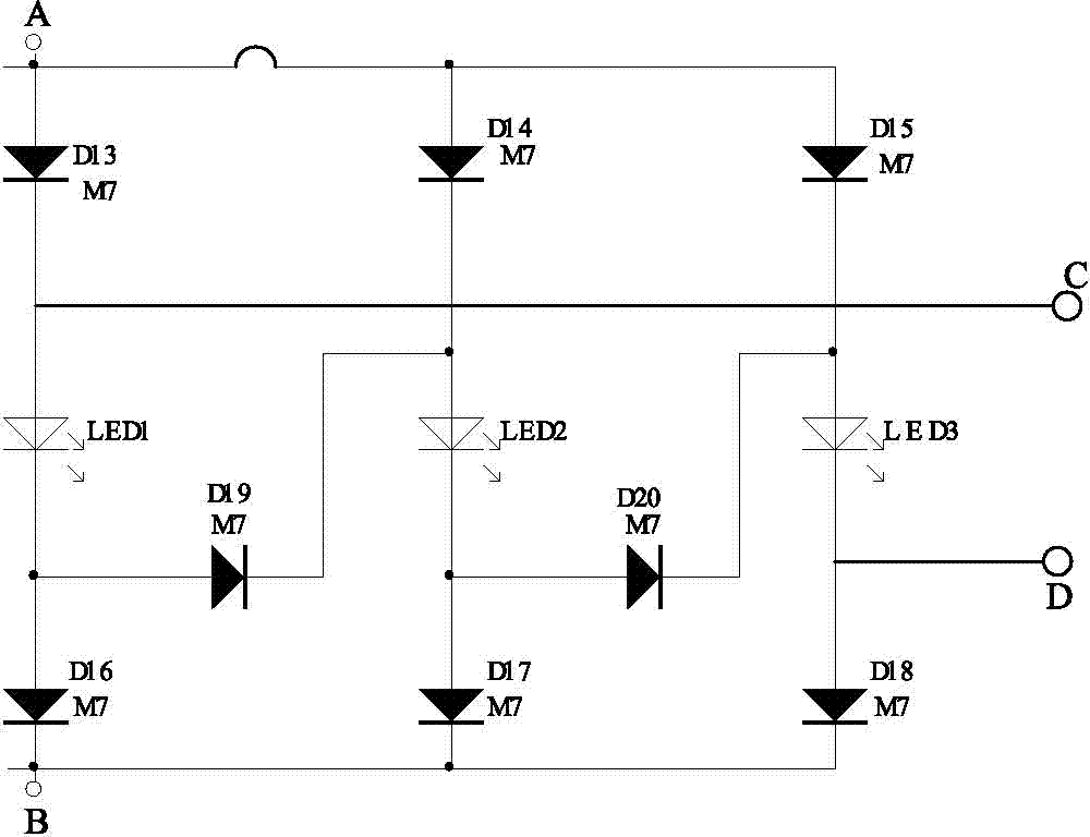
[0021] Such as figure 2 As shown, the load circuit includes input terminals A,...


PUM


Abstract

An electronic ballast based LED lamp tube comprises a load circuit, an AC/DC conversion circuit, a stroboflash-preventing circuit, a separation circuit and a compatible electronic ballast power circuit, wherein the load circuit comprises an input end A, an input end B, an input end C and an input end D, a plurality of mutually-parallel LED lamp branch circuits are arranged between the input end A and the input end B, and each LED lamp branch circuit comprises a first diode, an LED lamp and a second diode which are sequentially connected in series. The positive pole of the first diode is connected with the input end A, the negative pole of the second diode is connected with the input end B, third diodes are arranged among the LED lamp branch circuits, the positive poles of the third diodes are connected with the negative pole of the LED lamp of one LED lamp branch circuit, and the negative poles of the third diodes are connected with the positive pole of the other LED lamp branch circuit. LED lamps in the load circuit are mutually connected in series through the third diodes to form an LED serially-connected unit, and the input end C and the input end D are connected to two ends of the LED serially-connected unit.

Description

technical field [0001] The invention relates to the field of LED lighting, in particular to an LED lamp tube based on an electronic ballast. Background technique [0002] LED light tubes are also commonly known as LED light tubes, LED fluorescent tubes, and LED fluorescent lamps, and their light sources use LEDs as illuminants. Traditional fluorescent tubes are also called fluorescent lamps. There is a filament at each end of the lamp. The tube is filled with a small amount of argon and thin mercury vapor. The inner wall of the tube is coated with fluorescent powder. The gas between the two filaments emits ultraviolet rays when conducting electricity. Make phosphors emit visible light. Due to the heavy metal pollutant "mercury", the scrapped fluorescent tubes pollute the environment very seriously. The LED lamp uses light-emitting diodes as the light source, which has higher luminous efficiency, more energy-saving, longer service life, and is more environmentally friendly....

Claims


Application Information

Patent Timeline
Patent Type & Authority Applications(China)
IPC IPC(8): H05B37/02
Inventor 李高黄用国陈桂成黄漄静田阳
Owner GUANGZHOU LEDIA LIGHTING CO LTD
Why Eureka
Try Eureka