Frequency-flicker-free LED filament lamp

An LED filament lamp, no stroboscopic technology, which is applied in the use of semiconductor lamps, cooling/heating devices of lighting devices, lighting and heating equipment, etc. The effect of small size, simple circuit structure and high constant current precision

Active Publication Date: 2017-01-11
ZHEJIANG SUNSHINE MEIJIA LIGHTING CO LTD
View PDF5 Cites 7 Cited by
  • Summary
  • Abstract
  • Description
  • Claims
  • Application Information

AI Technical Summary

Problems solved by technology

Among them, the RC step-down drive power supply has fewer components, simple structure, and small size, but it will cause serious flickering of the LED filament, which is not conducive to human health; although the switching power supply type has no flickering problem, but There are many components, the structure is complex, and the volume is large, which is difficult to accommodate in the inner cavity of a small metal lamp holder; the linear constant current drive power supply has few components, the structure is relatively simple, the price is relatively low, and the dimming range is large. It can be accommodated in the inner cavity of a small metal lamp holder, but the stroboscopic problem of the LED filament is not serious, but it still exists and needs to be improved, and the power consumption is large, resulting in a large amount of heat. Although the existing heat dissipation measures can be used to make the drive The temperature of the power supply will not increase, but the structure of the existing heat dissipation structure is complicated

Method used


Image

  • Frequency-flicker-free LED filament lamp
  • Frequency-flicker-free LED filament lamp
  • Frequency-flicker-free LED filament lamp

Examples


Embodiment 1

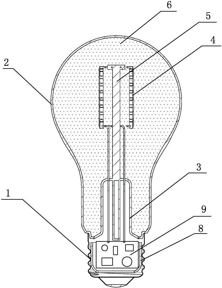
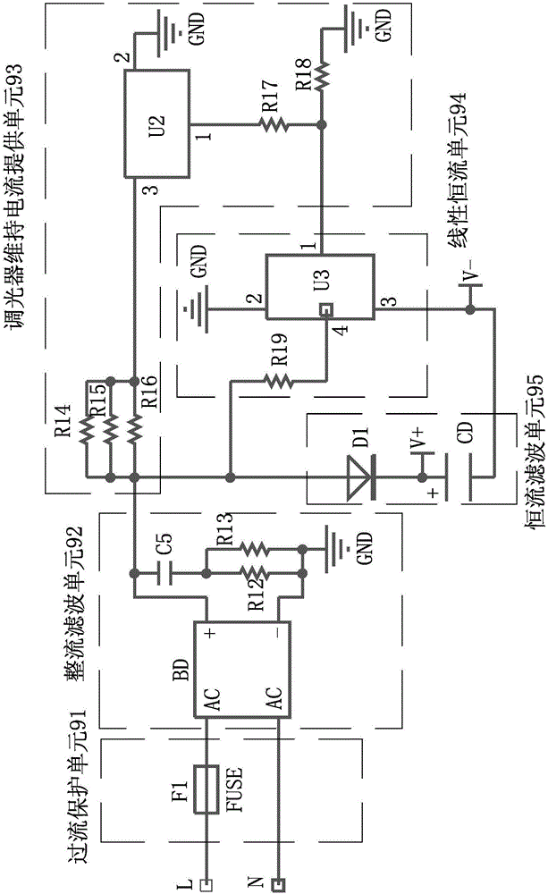
[0023] A kind of flicker-free LED filament lamp that present embodiment proposes, such as figure 1 , figure 2 and image 3 As shown, it includes a metal lamp cap 1, a glass bulb 2, a linear constant current driving power supply 9 arranged in the inner cavity of the metal lamp cap 1, a stem 3, an LED illuminant 4, a dimmer (not shown in the figure) Out), the top of the stem 3 is provided with a bracket 5, the LED illuminant 4 is installed on the bracket 5, the stem 3 loaded with the LED illuminant 4 is placed in the glass bulb 2, and forms a sealed seal with the glass bulb 2 Cavity 6, the airtight cavity 6 is filled with dry air, inert gas (such as nitrogen, argon, etc.) The drive power 9 in the inner cavity of the metal lamp cap 1 is connected, the metal lamp cap 1 and the glass bulb 2 are bonded and fixed, and the drive power 9 is maintained by an overcurrent protection unit 91, a rectification filter unit 92, and a dimmer connected to the dimmer. A current supply unit 93...

Embodiment 2

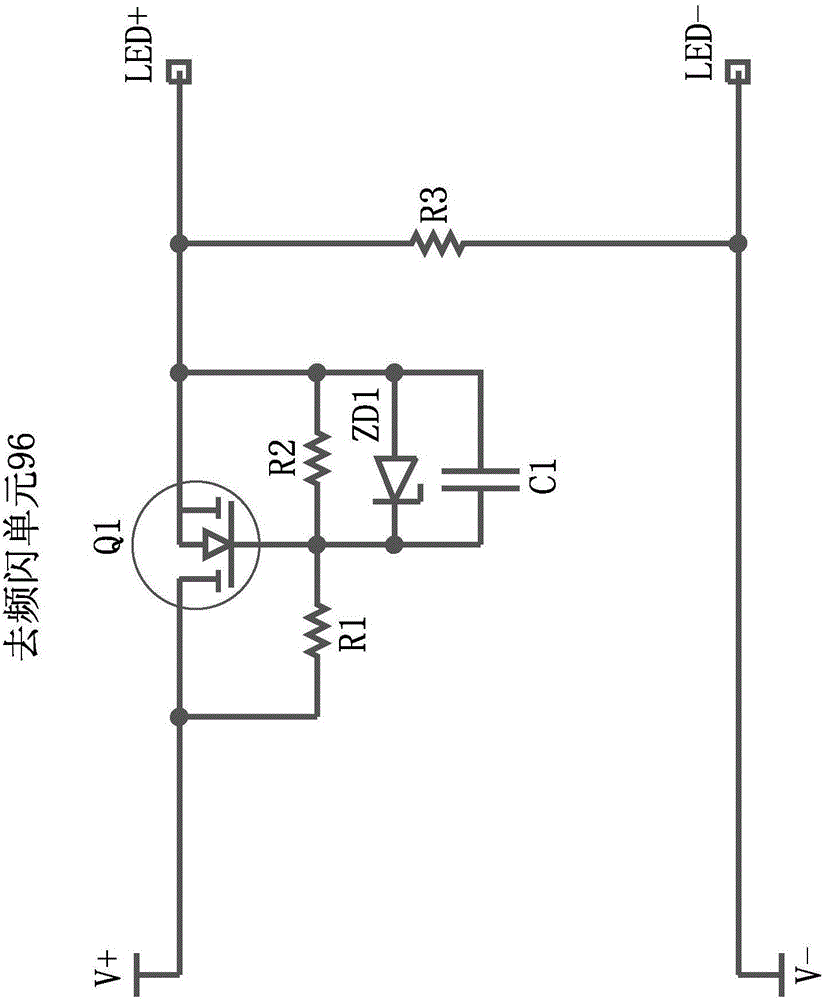
[0027] The flicker-free LED filament lamp proposed in this embodiment has the same other structures as the flicker-free LED filament lamp in Embodiment 1, except that the flicker-removing unit 96 is a flicker-removing circuit using a chip. Such as Figure 4 As shown, the anti-flicker circuit using the chip includes the first constant current chip U1 of the model YK3123, the fourth resistor R4, the fifth resistor R5, the sixth resistor R6, the seventh resistor R7, the eighth resistor R8, and the ninth resistor R9, the tenth resistor R10, the eleventh resistor R11, the second capacitor C2, the third capacitor C3 and the fourth capacitor C4, the first pin of the first constant current chip U1 is connected to one end of the fifth resistor R5, the first constant current The second pin of the flow chip U1 is respectively connected to one end of the sixth resistor R6, one end of the seventh resistor R7, one end of the eighth resistor R8, one end of the ninth resistor R9 and one end o...

Embodiment 3

[0029] A flicker-free LED filament lamp proposed in this embodiment further improves the structure of the flicker-free LED filament lamp in embodiment 1 or embodiment 2, see figure 1 That is, a heat dissipation structure capable of effectively dissipating heat to the driving power supply 9 is also added. The heat dissipation structure is a heat dissipation layer 8 formed by a layer of heat dissipation material wrapped outside the surface of the driving power supply 9. The driving power supply 9 wrapped with the heat dissipation layer 8 is placed on the metal In the inner cavity of the lamp cap 1, the heat dissipation layer 8 is in contact with the inner wall of the metal lamp cap 1, so that the heat of the driving power supply 9 is transferred to the metal lamp cap 1 through the heat dissipation layer 8, and the heat dissipation material is heat dissipation mud or heat dissipation glue. The heat of the heat can be transferred to the metal lamp holder 1 through the heat-conducti...


PUM


Abstract

The invention discloses a frequency-flicker-free LED filament lamp comprising a linear constant-current drive power supply and an LED luminous body. The drive power supply is composed of an over-current protection unit, a rectifier and filter unit, a linear constant-current unit, a constant-current filter unit, and a frequency flicker elimination unit used for converting the output current of the constant-current filter unit into direct current without current ripple. AC mains power is connected into the input end of the over-current protection unit. The output end of the over-current protection unit is connected with the input end of the rectifier and filter unit. The output end of the rectifier and filter unit is connected with the input end of the linear constant-current unit. The output end of the linear constant-current unit is connected with the input end of the constant-current filter unit. The output end of the constant-current filter unit is connected with the input end of the frequency flicker elimination unit. The output end of the frequency flicker elimination unit is connected with the LED luminous body. The advantage lies in that because of the introduction of the frequency flicker elimination unit, current ripple of constant current is eliminated, the precision of constant current is high, and therefore, there is no frequency flicker during light emission of the LED high-voltage filament in the LED luminous body.

Description

technical field [0001] The invention relates to an LED filament lamp, in particular to a flicker-free LED filament lamp. Background technique [0002] The LED filament is formed by bonding and connecting many ultraviolet or blue LED chips in series on the strip substrate, and then wrapping the strip substrate and the ultraviolet or blue LED chips with phosphor glue, and the ultraviolet or blue LED chips emit light with the phosphor powder. Combined into lighting white light, the working voltage of the LED filament is generally around 30-80V. [0003] LED filament lamps are becoming more and more popular, especially in Europe and America. LED filament lamps generally include a transparent bulb, a metal lamp cap, LED filament and a driving power supply. The LED filament is located in the transparent bulb, and the driving power is placed in the inner cavity of the metal lamp cap. The metal lamp cap is connected to the mouth of the transparent bulb. Since ultraviolet or blue L...

Claims


Application Information

Patent Timeline
Patent Type & Authority Applications(China)
IPC IPC(8): H05B33/08F21K9/232F21K9/238F21V23/02F21V23/04F21V29/508F21V29/85F21Y115/10H05B44/00
CPCF21V23/02F21V23/04F21V29/508F21V29/85H05B45/395H05B45/10Y02B20/30
Inventor 钟玲祥李阳徐泉江
Owner ZHEJIANG SUNSHINE MEIJIA LIGHTING CO LTD
Why Eureka
Try Eureka