Fixing rack for supporting oil pipeline

An oil pipeline and fixing frame technology, applied in the field of support frame, can solve the problems of large contact surface between the pipe groove and the oil pipeline, unstable placement of the oil pipeline, unadjustable height of the pipeline support frame, etc., so as to avoid distortion and strengthen the L The effect of the type bracket

Active Publication Date: 2015-07-01
嘉兴力度五金科技股份有限公司
View PDF6 Cites 16 Cited by
  • Summary
  • Abstract
  • Description
  • Claims
  • Application Information

AI Technical Summary

Problems solved by technology

[0003] In order to solve the defects such as the non-adjustable height of the pipeline support frame, the large contact surface between the pipe groove and the oil pipeline, and the unstable placement of the oil pipeline, the present invention provides a fixed frame for supporting the oil pipeline

Method used


Image

  • Fixing rack for supporting oil pipeline
  • Fixing rack for supporting oil pipeline

Examples


Embodiment 1

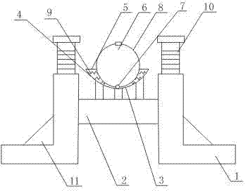
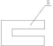
[0014] Such as figure 1 , figure 2 As shown, a fixed frame for supporting oil pipelines includes an L-shaped bracket 1, a base 2 arranged between two L-shaped brackets 1, and a support device 3 fixed on the base 2; the support device 3 includes an arc-shaped shell 4 and the horizontal plates 5 respectively connected to the two ends of the arc-shaped shell 4, one side of the horizontal plate 5 has a cuboid groove; it also includes a hoop 6, which includes two semicircular shells connected by hinges 7 8. The hoop 6 is located in the arc-shaped shell 4, and the hinge 7 is fixed on the bottom of the arc-shaped shell 4; wherein, the two semicircular shells 8 connected by the hinge 7 are respectively slidably arranged in the cuboid concave of the horizontal plate 5. In the groove; Also comprise some springs 9 that are respectively arranged on both sides inside the arc shell 4, one end of the spring 9 is connected on the inner wall of the arc shell 4, and the other end is connected...

Embodiment 2

[0017] In this embodiment, on the basis of Embodiment 1, the L-shaped bracket 1 is composed of a horizontal section and a vertical section. It has internal threads; it also includes a screw rod 10 set in the groove of the cylinder through threaded connection; it also includes a connecting rod connected to the screw rod 10 through a bearing, a slit is opened on the side of the vertical section, and the base 2 is fixed on the connection through the slit on the pole.

[0018] In this embodiment, the connecting rod is fixed on the screw rod 10 through a bearing, the base 2 is fixed on the connecting rod through a slit, and the screw rod 10 is slidably arranged in the vertical section through screw connection. Therefore, fine adjustment of the height of the oil pipeline support frame can be realized by rotating the screw rod 10 .

Embodiment 3

[0020] On the basis of Embodiment 2, this embodiment also includes a rib 11 connected to the L-shaped bracket 1. The rib 11 is a triangular column structure, and the two sides of the rib 11 are respectively fixed on the vertical section and the horizontal section of the L-shaped bracket 1. superior.

[0021] The rib plate 11 in this embodiment plays a role of strengthening the L-shaped bracket 1 and at the same time prevents the L-shaped bracket 1 from twisting and deforming under the action of external pressure.


PUM


Abstract

The invention provides a fixing rack for supporting an oil pipeline. The fixing rack comprises L-shaped supports, a base arranged between the two L-shaped supports and a supporting device fixed on the base. The supporting device comprises an arc-shaped shell and horizontal plates which are connected to the two ends of the arc-shaped shell respectively, and a cuboid groove is formed in one side of each horizontal plate. The supporting device further comprises a hoop which comprises two semicircular shell bodies connected through a hinge, the hoop is placed in the arc-shaped shell, and the hinge is fixed at the bottom of the arc-shaped shell. The semicircular shell bodies which are connected through the hinge are arranged in the cuboid grooves of the horizontal plates in a sliding mode respectively. The supporting device further comprises a plurality of springs which are arranged on the two sides inside the arc-shaped shell, one end of each spring is connected to the inner wall of the arc-shaped shell, and the other end of the corresponding spring is connected to the outer wall of the corresponding semicircular shell body. According to the fixing rack for supporting the oil pipeline, the springs are connected between the arc-shaped shell and the semicircular shell bodies, and the compressed springs give supporting force to the arc-shaped shell, so that the oil pipeline can be stably placed in the hoop.

Description

technical field [0001] The invention relates to a support frame, in particular to a fixed frame for supporting oil pipelines. Background technique [0002] During oil transportation, oil pipelines are usually laid off the ground. Therefore, oil pipeline support frames are provided at intervals to support the oil pipelines. However, in oil transportation, the support frame of the oil pipeline is generally erected at a certain height from the ground. If the height of the oil pipeline needs to be adjusted, the support usually needs to be reinstalled, which is time-consuming and laborious; It is supported in the pipe groove, and the cross-sectional shape of the pipe groove is generally the same as the cross-sectional shape of the pipe, which is roughly an arc shape. However, in this case, the contact surface between the pipe groove and the oil pipeline is relatively large, which makes the processing of the pipe groove difficult. If the processing is not good, the oil pipeline w...

Claims


Application Information

Patent Timeline
Patent Type & Authority Applications(China)
IPC IPC(8): F16L3/10F16M11/04
CPCF16L3/1075
Inventor 贺昶明
Owner 嘉兴力度五金科技股份有限公司
Why Eureka
Try Eureka