Mold clamping device

A clamping device and mold technology, applied in the direction of forming tools, manufacturing tools, presses, etc., can solve the problems of no fine-tuning function, high cost, cumbersome operation, etc., to increase the scope of use, facilitate processing, facilitate installation and clamping effect

Inactive Publication Date: 2016-07-27
CHANGZHOU JINCHENGYU HARDWARE
View PDF10 Cites 11 Cited by
  • Summary
  • Abstract
  • Description
  • Claims
  • Application Information

AI Technical Summary

Problems solved by technology

[0003] Existing factories will use molds to produce workpieces in large quantities, and molds need fixtures to fix them. Most of the existing mold fixtures are complicated and cumbersome to operate, and the design of the fixtures corresponding to the molds appears to be simplistic. Maybe one kind of

Method used


Image

  • Mold clamping device
  • Mold clamping device

Examples


Example Embodiment

[0013] The technical solutions in the embodiments of the present invention will be clearly and completely described below in conjunction with the accompanying drawings in the embodiments of the present invention. Obviously, the described embodiments are only a part of the embodiments of the present invention, rather than all the embodiments. Based on the embodiments of the present invention, all other embodiments obtained by those of ordinary skill in the art without creative work shall fall within the protection scope of the present invention.
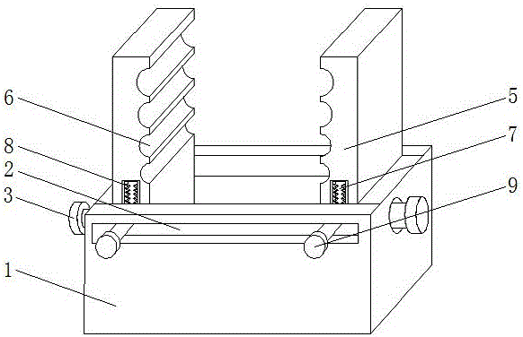
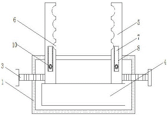
[0014] See Figure 1-2 , The present invention provides a technical solution: a clamping device for a mold, comprising a base 1, a rectangular hole 2 is provided on the front surface of the base 1, a first bolt 3 is provided on both sides of the base 1, and the first bolt 3 The end of the base passes through the side of the base 1 and extends to the inside of the base 1. Both sides of the base 1 are provided with bolt holes adapted to th...


PUM


Abstract

The invention discloses a mold clamping device. The mold clamping device comprises a base; a rectangular hole is formed in the front surface of the base; first bolts are respectively arranged on two sides of the base; the ends of the first bolts penetrate through the side surface of the base, and extend into the base; a slide plate is arranged in the base, and is provided with chutes; two clamping plates are arranged on the slide plate; the clamping plates are positioned in the chutes, penetrate through the top of the base, and extend above the base; and one sides, near the inner wall of the base, of the clamping plates are in threaded connection with the ends of the first bolts extending into the base. The mold clamping device can clamp different molds through setting first grooves to widen the application range, can move the clamping plates left and right through setting the first bolts to conveniently mount and clamp the molds, and can move the clamping plates up and down through setting second bolts to achieve the fine adjustment effect of the molds and convenience for machining.

Description

technical field [0001] The invention relates to the technical field of mold processing, in particular to a mold clamping device. Background technique [0002] A fixture is a device used to fix the processing object in the process of mechanical manufacturing so that it occupies the correct position for construction or inspection. [0003] Existing factories will use molds to produce workpieces in large quantities, and molds need fixtures to fix them. Most of the existing mold fixtures are complicated and cumbersome to operate, and the design of the fixtures corresponding to the molds appears to be simplistic. Maybe one kind of mold needs one kind of fixture, so The scope of use of fixtures is small, and some fixture designs require high costs. At the same time, some fixtures only have the function of fixed clamping and do not have the function of fine-tuning, which brings inconvenience to processing and manufacturing. Contents of the invention [0004] The object of the pr...

Claims


Application Information

Patent Timeline
IPC IPC(8): B21D37/04B30B15/02
CPCB21D37/04B30B15/026
Inventor 陆中明
Owner CHANGZHOU JINCHENGYU HARDWARE
Why Eureka
Try Eureka