Neutral-point voltage regulation method for three-phase three-level inverter

A three-level inverter and voltage regulation technology, which is applied in the direction of electrical components, output power conversion devices, AC power input conversion to DC power output, etc., can solve the problem of affecting motor speed regulation performance, increasing voltage, and reducing system reliability. sexual issues

Inactive Publication Date: 2015-07-01
上海兆能电力电子技术有限公司
View PDF3 Cites 2 Cited by
  • Summary
  • Abstract
  • Description
  • Claims
  • Application Information

AI Technical Summary

Problems solved by technology

However, this kind of converter uses two capacitors connected in series to generate three levels. Due to the inconsistency of the characteristics of the switching device itself and the midpoint potential participating in the energy transmission during the energy conversion of the converter, the voltage division of the two capacitors will be different. average problem, that is, the midpoint balance problem
If the midpoint potential is unbalanced, low-order harmonics will be generated on the AC output side, which will reduce the output efficiency of the inverter. Some switching tubes of the transformer are subjected to higher voltage, which reduces the reliability of the system; finally, the midpoint potential fluctuation reduces the life of the DC side capacitor

Method used


Image

  • Neutral-point voltage regulation method for three-phase three-level inverter
  • Neutral-point voltage regulation method for three-phase three-level inverter
  • Neutral-point voltage regulation method for three-phase three-level inverter

Examples


Embodiment Construction

[0030] The specific embodiments of the present invention will be described below in conjunction with the drawings.

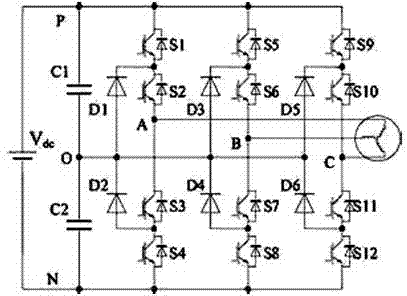
[0031] figure 1 The example provides a typical circuit topology diagram of a three-phase three-level inverter. The midpoint voltage adjustment method of the present invention is suitable for three-phase three-level inverters and similar ones with three DC inputs Level, the power electronic system that outputs three-phase voltage.

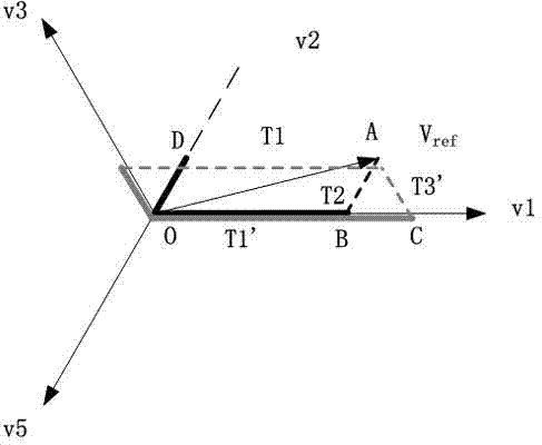
[0032] In the output relationship of the three-level inverter, the three-phase three-level voltage vector satisfies the following relationship:

[0033]

[0034]

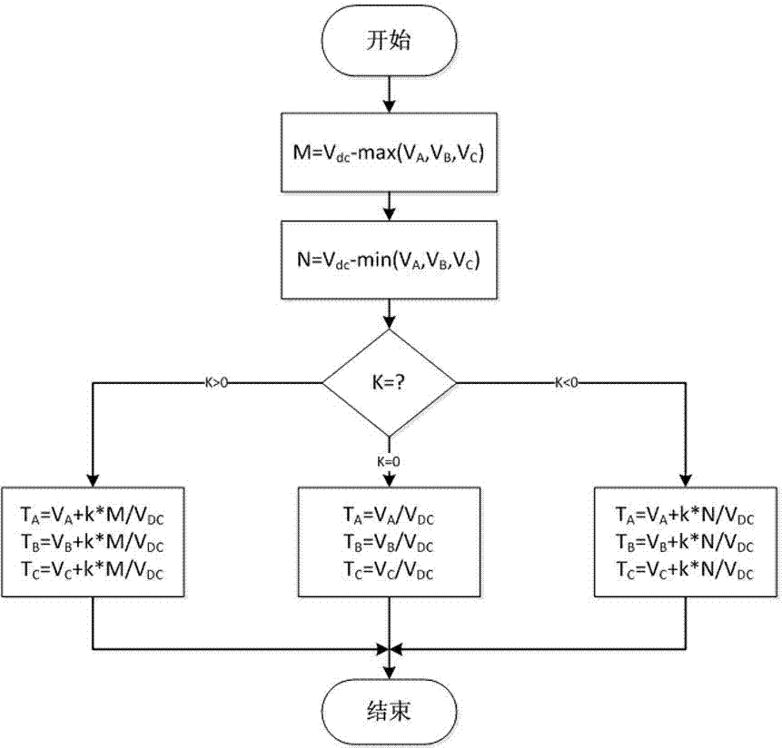
[0035] among them, Is the current input reference voltage vector, It is the voltage vector of the inverter's three-phase bridge arm corresponding to the calculated PWM (Pulse Width Modulation) period. T PWM Is the pulse width modulation period, T A ,T B ,T C They are the control time of the three voltage bridge arms of the three-phase three-level inverter, and the control tim...


PUM


Abstract

The invention relates to a neutral-point voltage regulation method for a three-phase three-level inverter. The method includes: according to a difference between a direct-current-side voltage and each of a maximum voltage value and a minimum voltage value of a three-phase bridge arm of the three-level inverter, calculating a numerical value which can be added to or subtracted from a voltage vector, corresponding to a PWM (pulse-width modulation) period, o f the three-phase bridge arm; obtaining control time of a switching device in the three-phase bridge arm according to a given neutral-point voltage regulation coefficient; comparing the control time with a carrier wave according to a PWM modulation rule of the three-level inverter to generate a control instruction for driving the switching device in the three-level inverter. Neutral-point voltage regulation and control are realized by means of selection of switch variables, and easiness in implementation and effectiveness in improvement of operation efficiency are realized.

Description

Technical field [0001] The invention relates to the field of inverter control, in particular to a midpoint voltage adjustment method for controlling a three-phase three-level inverter. Background technique [0002] Multi-level inverters are suitable for large-capacity and high-voltage occasions, and have been increasingly used. The three-level inverter has a plurality of switching components, and the switching combination of the components is configured as the output voltage of the inverter. The different combinations of the switching states of multiple switching components are set to provide the voltage space vector of the output voltage. With this topology, the maximum voltage that each power switch can withstand is 1 / 2 of the DC side voltage. In addition, due to the phase The voltage has three level states, one more level than the traditional two-level inverter, so the output waveform quality is high. Therefore, this structure converter has a wide range of applications in hi...

Claims


Application Information

Patent Timeline
Patent Type & Authority Applications(China)
IPC IPC(8): H02M7/487H02M7/5395
CPCH02M7/487H02M7/5395
Inventor 李丹郑洪涛
Owner 上海兆能电力电子技术有限公司
Why Eureka
Try Eureka