Flapping door unit transmission mechanism and flapping door unit

A technology of transmission mechanism and flapping door, which is applied in the direction of power control mechanism, gate/door, wing leaf control mechanism, etc., which can solve the problem that the direct connection scheme of the control motor drive shaft and the flapping door rotating shaft cannot be adopted, and the flapping door unit cannot be guaranteed to be vertical. For problems such as the horizontal base of the gate installation, the limited height of the gate or the internal space of the automatic ticket gate, it can save maintenance time and labor costs, save maintenance time, and save installation space.

Pending Publication Date: 2018-11-30
艾弗世(苏州)专用设备股份有限公司
View PDF8 Cites 2 Cited by
  • Summary
  • Abstract
  • Description
  • Claims
  • Application Information

AI Technical Summary

Problems solved by technology

[0006] 1. Restricted by the overall height of the gate or automatic ticket gate (equipment height has relevant industry regulations), when the flapping gate unit is assembled into the gate or automatic ticket gate, due to limited space, it cannot ensure that it is installed perpendicular to the gate The base surface is horizontal, causing the flapping door leaf to tilt and rotate, which affects the overall appearance of the equipment
[0007] 2. Limited by the overall height of the gate or automatic ticket gate, it is impossible to adopt a direct connection scheme that controls the drive shaft of the motor and the shaft of the flapping door to keep vertical
[0008] 3. Limited by the height of the inner space of the gate or automatic ticket gate, it is impossible to adopt the solution of co-existence of electromagnetic brake and motor. Therefore, in the flapping gate units currently used in the industry, there are often only motors without electromagnetic brakes
After the lack of electromagnetic brake, the brake of the gate can only be braked and locked by the reverse and locked rotor of the motor itself, which greatly reduces the movement accuracy and braking accuracy of the flapping door
[0009] 4. When the motor and the electromagnetic brake fail, the door unit must be disassembled as a whole before the electromagnetic brake and the motor can be disassembled and repaired if the scheme of direct connection with the drive shaft of the flapping door is adopted, which wastes manpower and time and leads to a high cost of the direct connection scheme. maintenance cost

Method used


Image

  • Flapping door unit transmission mechanism and flapping door unit
  • Flapping door unit transmission mechanism and flapping door unit
  • Flapping door unit transmission mechanism and flapping door unit

Examples


Embodiment 1

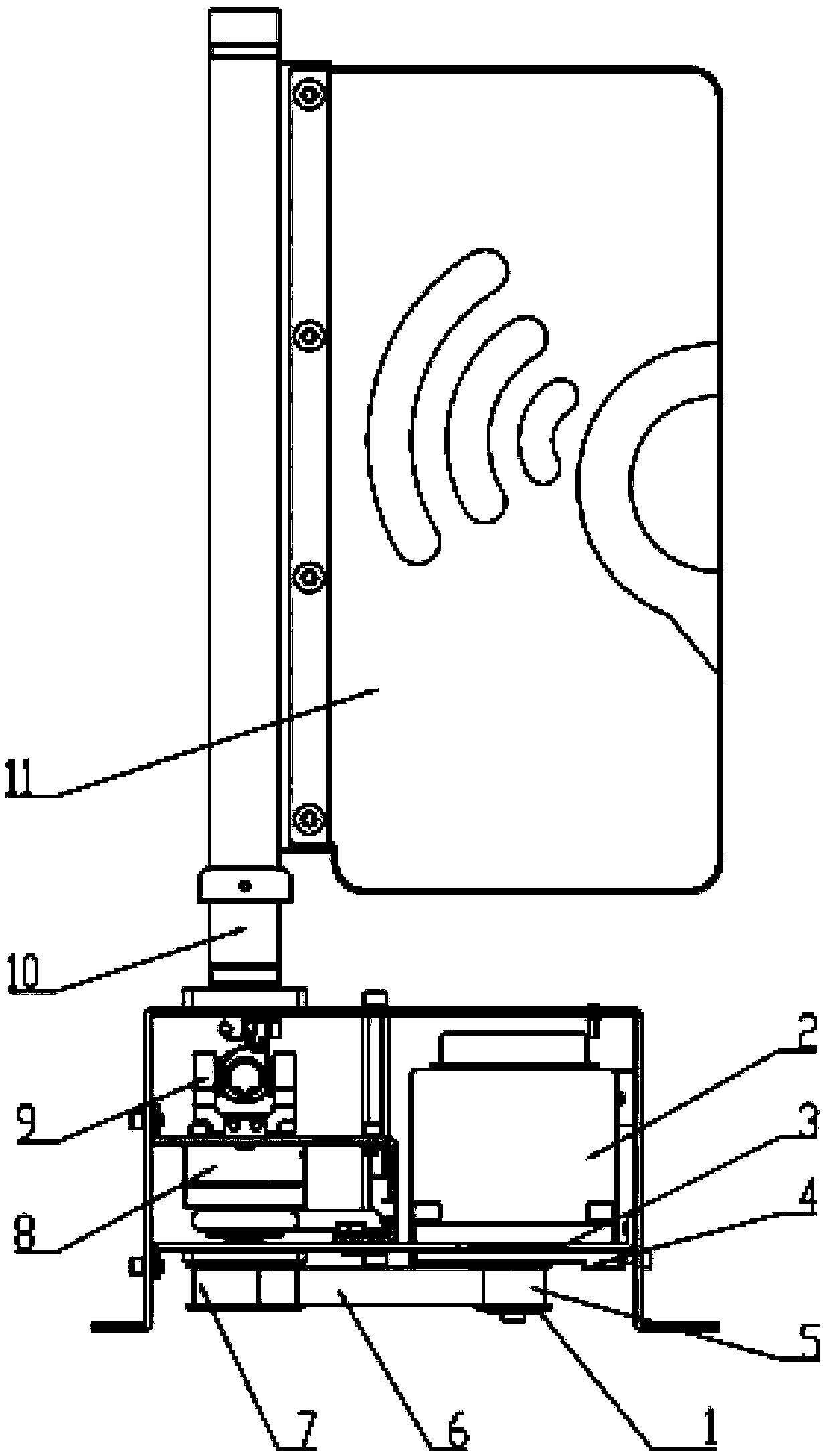
[0086] The driven synchronous pulley 7 is directly nested and installed with the flapping door rotating shaft 10, and the flapping door rotating shaft 10 is inserted into the central hole of the driven synchronous pulley 7, and the two are fixedly connected by splines or other forms, such as Figure 3-1 shown.

Embodiment 2

[0088] After installation using the structure of Embodiment 1, since the flapping gate unit depends on the appearance of the whole machine of the gate or automatic ticket gate, the installation position is relatively fixed. There may be cases of different axes, such as Figure 5 As shown, the axis A of the flapping door shaft and the axis B of the driven synchronous pulley's shaft are not on the same straight line, so it is impossible to directly form a transmission linkage. If it is barely connected, it cannot be efficiently transmitted to the flapping door shaft Motion and torque of the shaft from the driven timing pulley.

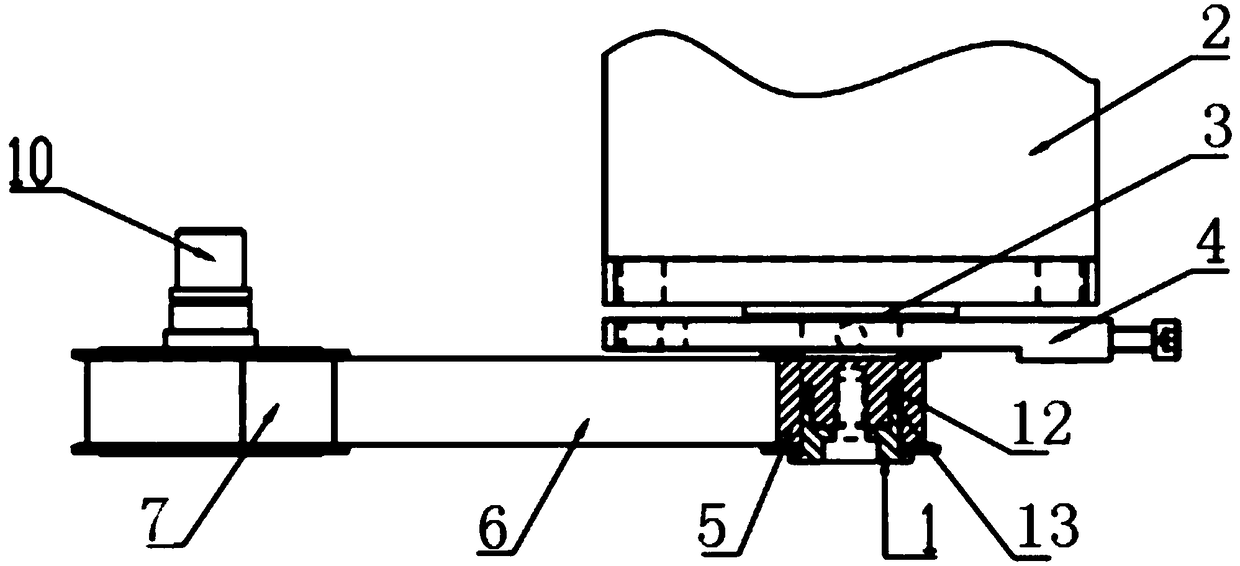
[0089] Now the preferred scheme is to connect the flapping door rotating shaft and the driven synchronous pulley 7 by the cross shaft universal joint. Rely on the cross shaft universal joint 9 to carry out the transmission linkage between the driven synchronous pulley 7 and the flapping door rotating shaft 10. The cross shaft universal joint is install...


PUM


Abstract

The invention provides a flapping door unit transmission mechanism and a flapping door unit, belongs to the field of access control, automatic ticket checking equipment and rail transit equipment. Theflapping door unit transmission mechanism is used in the flapping door unit, the flapping door unit includes a motor and a flapping door rotating shaft, and the transmission mechanism includes a drive synchronous pulley, a synchronous belt and a driven synchronous pulley. The drive synchronous pulley, the driven synchronous pulley and the synchronous belt are horizontally disposed. The axis of the drive synchronous pulley and the axis of the driven synchronous pulley are both perpendicular to the horizontal plane. The drive synchronous pulley and the driven synchronous pulley perform synchronous transmission through the synchronous belt, and the torque of a main shaft of the motor is transmitted to the flapping door rotating shaft. By using the flapping door unit transmission mechanism and the flapping door unit, the precision of the movement and braking of a flapping door is improved, the installation space is greatly saved, the cost of a gate machine is reduced, and the maintenancetime and labor cost are saved.

Description

technical field [0001] The invention belongs to the fields of access control, automatic ticket checking equipment and rail transit equipment, and in particular relates to a flapping door unit transmission mechanism and a flapping door unit. Background technique [0002] At present, the flapping door unit is widely used in the fields of access control, automatic ticket checking equipment, and rail transit equipment. The flapping door unit is an AFC special module integrating optical, mechanical and electrical technologies. It is installed in the gate as a blocking mechanism to effectively control the entry and exit behavior of pedestrians and passengers. Only those with legal authorization are allowed to pass. Provide fast ticket check-in and entry-exit services for passengers. [0003] The flapping door has a flapping door leaf that can be opened and closed under the control of the motor device, which can fully open and block the gate passage, and can also be completely clo...

Claims


Application Information

Patent Timeline
Patent Type & Authority Applications(China)
IPC IPC(8): E06B11/02E05F15/627
CPCE05F15/627E06B11/022
Inventor 杜潜王建坤李棋瑞高鹏飞郭建树齐春阳程明亮柳振强陈国林陈跃飞蔡晓曼李智超王子印贾利明陈苗苗杨丰高学朋樊荣韩建军
Owner 艾弗世(苏州)专用设备股份有限公司
Why Eureka
Try Eureka