Indoor positioning system and positioning method of distributed antenna system

A distributed antenna and indoor positioning technology, applied in indoor positioning system and its positioning field, can solve the problems of low connection quality and achieve the effect of maintaining connection quality

Inactive Publication Date: 2015-07-01
AMOESOLU
View PDF4 Cites 3 Cited by
  • Summary
  • Abstract
  • Description
  • Claims
  • Application Information

AI Technical Summary

Problems solved by technology

[0005] In view of the above-mentioned defects of the existing DAS system, the main purpose of the present invention is to provide an indoor positioning system of a distributed antenna system and its positioning method to solve the technical defects of low connection quality

Method used


Image

  • Indoor positioning system and positioning method of distributed antenna system
  • Indoor positioning system and positioning method of distributed antenna system
  • Indoor positioning system and positioning method of distributed antenna system

Examples


Embodiment Construction

[0033] The technical solution of the present invention will be described in detail below in conjunction with the accompanying drawings and specific embodiments to further understand the purpose, solution and effect of the present invention, but it is not intended to limit the scope of protection of the appended claims of the present invention.

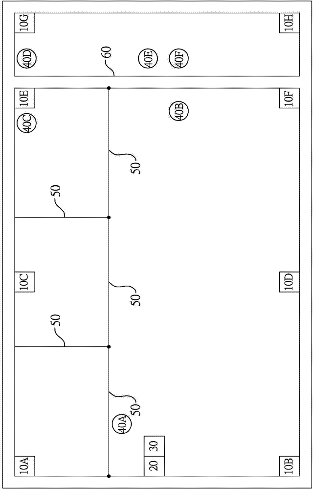
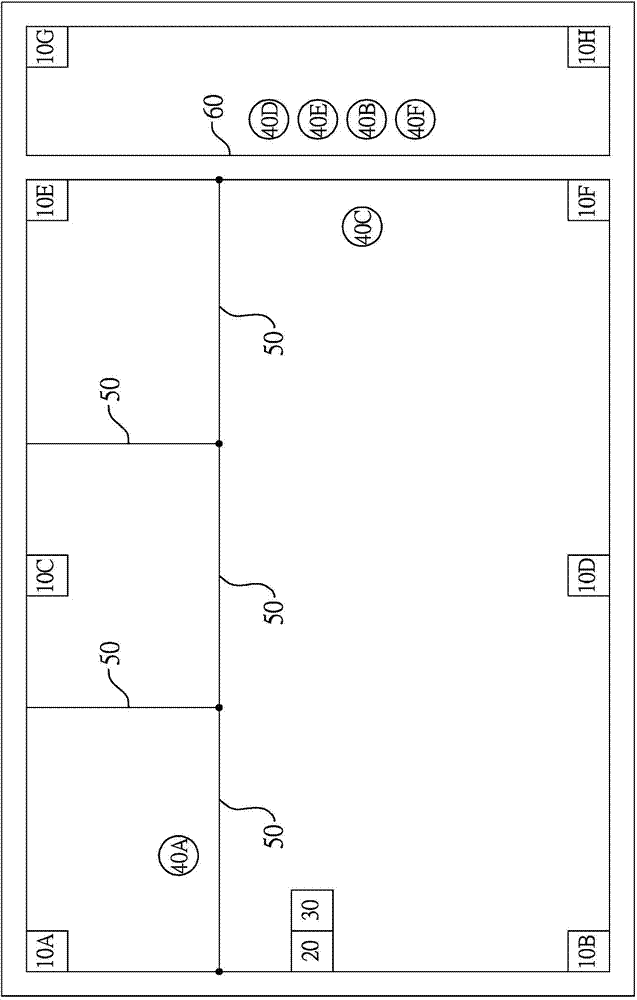
[0034] see Figure 1A and 1B As shown, a preferred embodiment of an indoor positioning system of a distributed antenna system in the present invention includes eight antenna terminals 10A-H, a head end 20 and a positioning unit 30 . Such as Figure 1A As shown, the indoor positioning system of the distributed antenna system is installed on a floor where a plurality of wooden partitions 50 and a cement wall 60 are distributed, and six user devices 40A-F are placed separately. The floors are in different locations to clearly illustrate the indoor communication positioning procedure of the present invention. and Figure 1B is representa...


PUM


Abstract

The invention provides an indoor positioning system and a positioning method of a distributed antenna system. The indoor positioning system is provided with multiple antenna terminals, a head end and a positioning unit. The head end allocates non-repeated communication frequency bands for user devices connected with the antenna terminals, the positioning unit reads the communication frequency bands occupied by the antenna terminals and network signal strength of the occupied communication frequency bands and then positions the positions of the user devices according to the occupied communication frequency bands and the network signal strength of the occupied communication frequency bands. Therefore, the distribution positions of the indoor user devices can be positioned, a manager of the floor can add antenna terminals at the positions where the user devices are often gathered in the floor so as to keep the network connecting quality at the positions.

Description

technical field [0001] The invention relates to a communication flow monitoring method and system thereof, in particular to an indoor positioning system and a positioning method of a distributed antenna system using a DAS system to monitor indoor communication flow. Background technique [0002] The so-called distributed antenna system (Distributed Antenna System; DAS) (hereinafter referred to as DAS system) has a head end and a plurality of antenna ends commonly connected to the head end, wherein the head end is connected to a network, and the antenna ends are respectively set Everywhere in an area, and the communication ranges of the antennas respectively cover every place in the area, so as to form a wireless network in the area. [0003] The DAS system can also be applied indoors, such as subways and high-rise buildings, where general wireless networks cannot reach. When each user device is connected to the DAS system, the head end allocates an unoccupied communication ...

Claims


Application Information

Patent Timeline
Patent Type & Authority Applications(China)
IPC IPC(8): H04W64/00
Inventor 许腾尹陈政言黄文杰简瑞祥叶邵颖
Owner AMOESOLU
Why Eureka
Try Eureka