V2x vehicle-mounted device and v2x relay
A technology of repeater and vehicle-mounted device, which is applied in the direction of communication between vehicles and infrastructure, instruments, vehicle components, etc., can solve problems such as the increase of communication traffic, and achieve the effect of preventing the increase of communication traffic.
- Summary
- Abstract
- Description
- Claims
- Application Information
AI Technical Summary
Problems solved by technology
Method used
Image
Examples
Embodiment approach 1
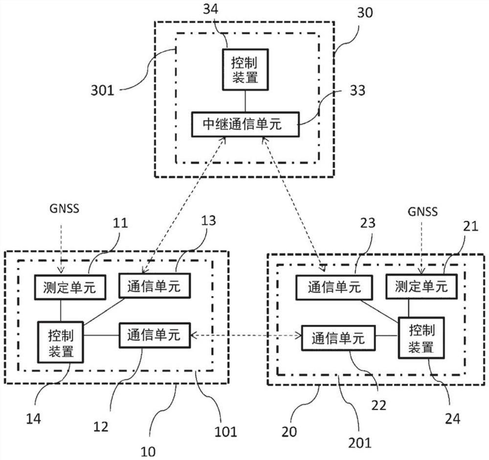
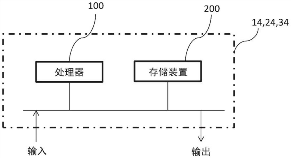
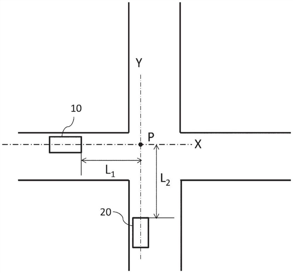
[0034] figure 1 is an overall configuration diagram of the V2X communication system in Embodiment 1, figure 2 is carried on figure 1 A hardware structure diagram of the control devices on the V2X vehicle-mounted devices 101 and 201 in the V2X communication system of , image 3 It is a diagram showing the positional relationship of vehicles when the V2X communication system is applied to the intersection collision avoidance warning system, Figure 4 It is a flowchart for explaining the operation of the V2X vehicle-mounted devices 101 and 201 and the V2X repeater 301 taking the intersection collision avoidance warning system as an example.
[0035] use figure 1 The V2X communication system according to Embodiment 1 will be described. In Embodiment 1, this V2X communication system is used in an intersection collision avoidance warning system described below. The V2X on-board devices 101 and 201 of the vehicle 10 and the vehicle 20 are equipped with measurement units 11 and ...
Embodiment approach 2
[0058] In Embodiment 1, in the transmission necessity determination process performed by the control device 14 of the vehicle 10, it is determined whether or not the range of the position or the heading of the own vehicle is included in the list of difficult-to-transmit areas received from the base station 30. In the area D where direct transmission is difficult, but this determination can also be made by the V2X relay 301 of the base station 30 . Here, the vehicle information and the direct transmission difficult area list are the same data as those in the first embodiment.
[0059] Figure 10 is in such Figure 5 As mentioned above, when the radio wave is blocked by the building 50 and the vehicle information is directly communicated from the vehicle 10, when the vehicle 10 enters the transmitted radio wave and does not reach the direct transmission difficult area D of the vehicle 20, the V2X relay of the base station 30 It is a time-sequence diagram in the case where the ...
Embodiment approach 3
[0065] In Embodiments 1 and 2, the direct transmission difficult area list is used to suppress transmission when relay is unnecessary, but the direct reception difficult area list may be held instead of the direct transmission difficult area list.
[0066] Below, use Figure 11 to Figure 13 To illustrate the direct reception of the list of difficult areas. Figure 11 An example of an area where reception is difficult is shown. When the slave vehicle 20 uses the communication unit 22 to simultaneously transmit by direct transmission, there is an area F where radio waves are blocked by buildings 50 in between and radio waves transmitted from the vehicle 20 cannot reach the vehicle 10 (hereinafter referred to as direct reception difficult area) F.
[0067] and Figure 5 with Figure 7 The direct sending difficult region shown is likewise the direct receiving difficult region F is as Figure 12 The area represented by a rectangular area of latitude and longitude is shown. S...
PUM
 Abstract
Description
Claims
Application Information
 - R&D
- Intellectual Property
- Life Sciences
- Materials
- Tech Scout
- Unparalleled Data Quality
- Higher Quality Content
- 60% Fewer Hallucinations
Browse by: Latest US Patents, China's latest patents, Technical Efficacy Thesaurus, Application Domain, Technology Topic, Popular Technical Reports.
© 2025 PatSnap. All rights reserved.Legal|Privacy policy|Modern Slavery Act Transparency Statement|Sitemap|About US| Contact US: help@patsnap.com


