A Magneto-rheological Valve Using Permanent Magnets and Double Coils for Composite Control

A technology of permanent magnets and magnetorheological valves, applied in the field of magnetorheological valves, can solve the problems of narrow pressure adjustment range, complex structure of magnetorheological valves, single adjustment method, etc., and achieve the increase or decrease of the pressure difference between the inlet and outlet , Flexible pressure regulation method and wide pressure regulation range

Active Publication Date: 2017-07-04
EAST CHINA JIAOTONG UNIVERSITY
View PDF4 Cites 0 Cited by
  • Summary
  • Abstract
  • Description
  • Claims
  • Application Information

AI Technical Summary

Problems solved by technology

However, the thickness of the damping gap of these types of magnetorheological valves is fixed and cannot be adjusted, so the pressure difference between the inlet and outlet of the valve can only be adjusted by controlling the current in the excitation coil within a certain range, the pressure adjustment range is narrow, and the adjustment method is single. It can be applied to a narrow range of damping force adjustment systems, thus hindering the development of industrial applications of magnetorheological valves
Although there are magnetorheological valves that change the size of the damping gap through mechanical adjustment, the structure of the magnetorheological valve is relatively complicated.
At the same time, some researchers have also proposed single-coil and double-coil radial flow magneto-rheological valves, which can effectively improve the size restriction of the working damping gap of the magnetorheological valve to a certain extent, and the pressure difference adjustment range is also wide, but The valve is used in the damping system. If the power fails, it is easy to fail immediately, and it cannot play the role of buffering and protecting the system under certain time and working conditions.
Therefore, the structure of the existing magnetorheological valve restricts its application in the bypass valve magnetorheological damper system

Method used


Image

  • A Magneto-rheological Valve Using Permanent Magnets and Double Coils for Composite Control
  • A Magneto-rheological Valve Using Permanent Magnets and Double Coils for Composite Control
  • A Magneto-rheological Valve Using Permanent Magnets and Double Coils for Composite Control

Examples


Embodiment Construction

[0021] The present invention will be further explained below in conjunction with the drawings and embodiments:

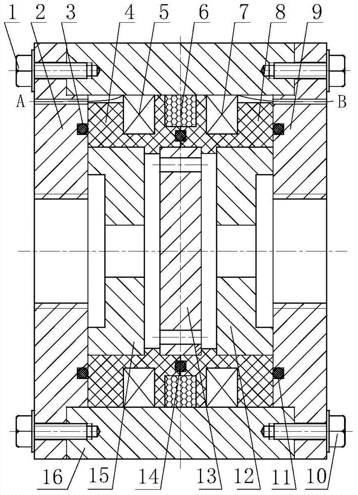
[0022] Such as figure 1 As shown, the present invention includes: screw I1, left end cover 2, sealing ring I3, left winding frame 4, excitation coil I5, permanent magnet 6, excitation coil II7, right winding frame 8, right end cover 9, screw II10, sealing Ring II11, right positioning disc 12, damping disc 13, sealing ring III14, left positioning disc 15 and valve body 16.

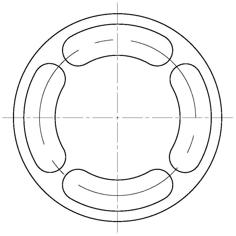
[0023] figure 2 Shown is a schematic diagram of the structure of the damping disc of the present invention. The damping disc 13 is processed with 4 waist-shaped through holes with the same structure and uniformly arranged to form a magnetorheological fluid flow channel.

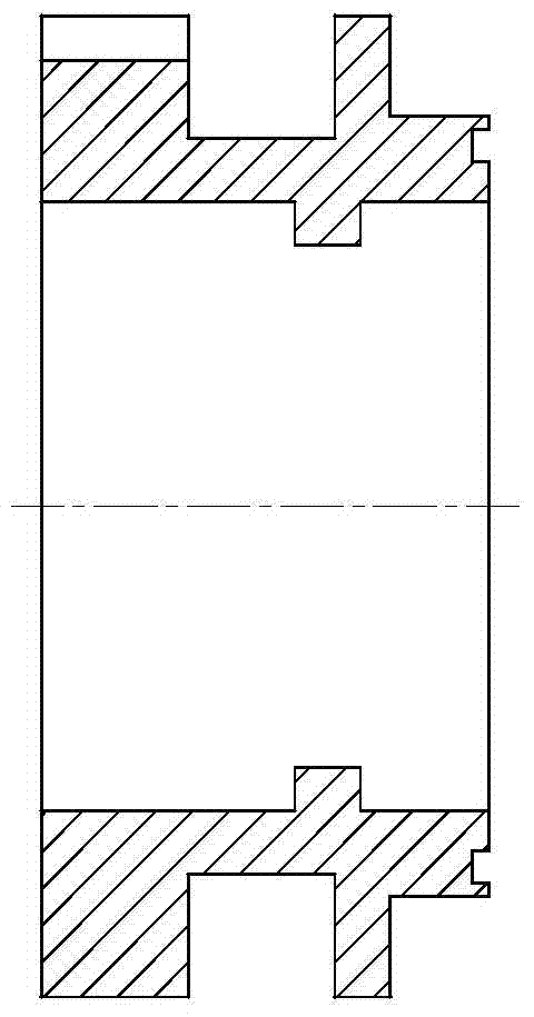
[0024] image 3 Shown is a schematic diagram of the structure of the left winding frame of the present invention, and the structure design of the left winding frame 4 and the right winding frame 8 are the same. The top of the left en...


PUM


Abstract

The invention discloses a magneto-rheological valve controlled by permanent magnets and double coils. The magnetic field generating device of the magneto-rheological valve is composed of a permanent magnet and a double coil. In the case of power failure, a fixed magnetic field is generated by the permanent magnet, so that the magneto-rheological valve still has a certain pressure difference between the inlet and outlet under zero current; The direction of the magnetic field is the same or opposite to the magnetic field generated by the permanent magnet, which acts to strengthen the magnetic field in the same direction or weaken the magnetic field in the opposite direction, so that the pressure difference between the inlet and outlet of the magnetorheological valve increases or decreases. The magneto-rheological valve is especially suitable for use as a bypass valve in the magnetorheological damper. Through the compound control of the permanent magnet and the double coil, the damping force of the magnetorheological damper can be adjusted in a wide range, with excellent fault performance and shock absorption. Cushioning works smoothly.

Description

Technical field [0001] The invention relates to a magnetorheological valve, in particular to a magnetorheological valve that adopts permanent magnets and double coils for compound control. Background technique [0002] Magnetorheological valve is a new type of hydraulic control valve using smart material magnetorheological fluid as working medium. Under the action of a magnetic field, the magnetorheological fluid can transform from a free-flowing Newtonian fluid to a viscoplastic body with a certain shear yield strength, and at the same time, it returns to a free-flowing liquid state after the magnetic field is removed. Based on this rheological characteristic, the inlet and outlet pressure of the magnetorheological valve can be controlled in real time by the applied current, which has the characteristics of high response speed, low energy consumption, stable and reliable operation, and has good application prospects. [0003] With the continuous maturity of the structural design ...

Claims


Application Information

Patent Timeline
Patent Type & Authority Patents(China)
IPC IPC(8): F16K13/10F16K31/08
CPCF16K13/10F16K31/08
Inventor 胡国良张海云李卫华
Owner EAST CHINA JIAOTONG UNIVERSITY
Why Eureka
Try Eureka