Flat light installation mechanism

An installation mechanism and a technology for flat lamps, which are applied in the direction of connecting components, mechanical equipment, lighting devices, etc., can solve the problems of wasted labor, labor hours, and inconvenient factory practices.

Active Publication Date: 2018-05-22
KUNSHAN CHENGTAI ELECTRIC
View PDF18 Cites 0 Cited by
  • Summary
  • Abstract
  • Description
  • Claims
  • Application Information

AI Technical Summary

Problems solved by technology

As a manufacturer of flat lamps, in order to meet all needs and prevent parts from being lost, the hook hanger and screws are generally tightened on the back of the flat lamp. For customers who use the flat lamp as a ceiling lamp, the flat lamp This kind of delivery method is quite practical, and it can be installed directly. However, for customers who use flat lights as other purposes than ceiling lights, they need to unscrew the screws and remove the hook hanging parts before installing. It is very inconvenient to do
Moreover, as a manufacturer, it is relatively labor-intensive to screw the two parts of the hook hanger and the screw on the back of the flat light, and for customers who do not need the hook hanger, the man-hours spent by the manufacturer are a waste

Method used


Image

  • Flat light installation mechanism
  • Flat light installation mechanism
  • Flat light installation mechanism

Examples


Embodiment 1

[0028] Embodiment 1: This embodiment is the best embodiment of the present invention. A flat light installation mechanism, such as Figure 4 to Figure 6 As shown, it is composed of a screw 1 and a hook hanger 2. There are two installation mechanisms and are arranged symmetrically at the back edge of the flat lamp. When the flat light leaves the factory, the screw 1 is screwed on the back A of the flat light, and the hook hanging member 2 is independent of the flat light, such as Figure 4 Shown.

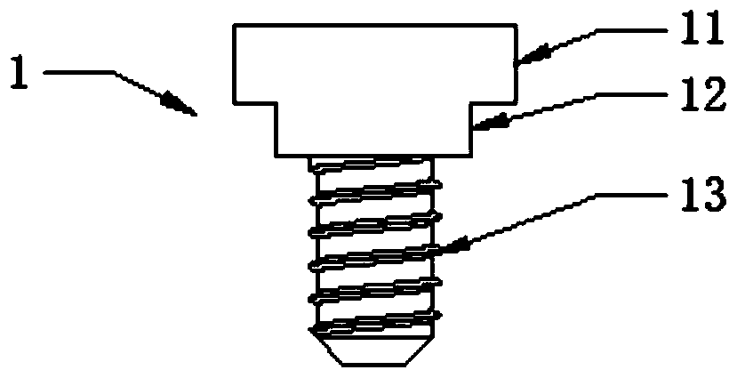
[0029] Such as figure 1 As shown, the screw 1 is integrally composed of a screw head 11, a clamping section 12, and a thread section 13. The clamping section 12 is integrally connected between the screw head 11 and the thread section 13, and the clamping section The diameter of 12 is smaller than the diameter of the screw head 11 and larger than the diameter of the thread segment 13. The screw head 11 is cylindrical, and the clip 12 is cylindrical.

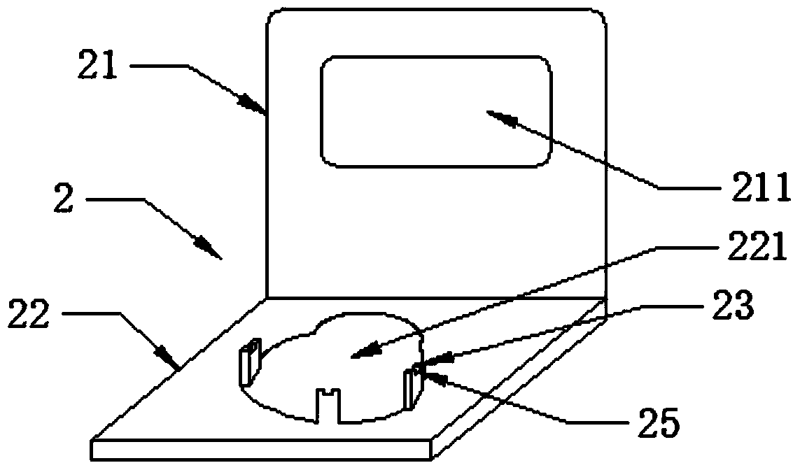
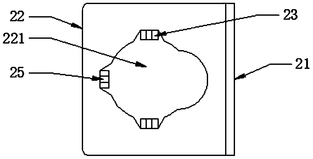
[0030] Such as figure 2 with imag...

Embodiment 2

[0033] Embodiment 2: The installation mechanism of this embodiment is substantially the same as that of Embodiment 1. This embodiment is a modification of Embodiment 1, and only the structure of the protection block is different. The protection block 24 in the installation mechanism of this embodiment, such as Figure 7 with Figure 8 As shown, it is a bendable strip member integrally connected to the junction of the large screw hole and the small screw hole. When the protection block 24 is perpendicular to the screw hole plate 22, the clip 12 of the screw 1 can move from the large screw hole of the hook hanger to the small screw hole, such as Figure 7 As shown; when the protection block 24 is bent to be in the same plane as the screw hole plate 22, the protection block 24 prevents the clamping section 12 of the screw 1 from moving from a small screw hole to a large screw hole, such as Figure 8 Shown.

Embodiment 3

[0034] Embodiment 3: The installation mechanism of this embodiment is substantially the same as that of Embodiment 1. This embodiment is a modification of Embodiment 1, except that the structure of the protection block is different. The protection block 3 of the installation mechanism of this embodiment, such as Picture 9 As shown, it is a plastic block, rubber block or silicone block independent of the hook hanger. The protective block 3 can be inserted into the large screw hole of the hook hanger 2 to prevent the screw 1 from being screwed. The head 11 passes through the large screw hole of the hook hanger 2, such as Picture 10 Shown.


PUM


Abstract

The invention discloses a flat lamp mounting mechanism. The flat lamp mounting mechanism is composed of a screw and a clamp hook hanger, the screw is composed of a screw head, a clamp section and a screw tooth section in an integrated mode, the diameter of the clamp section is smaller than that of the screw head and larger than that of the screw tooth section, the clamp hook hanger is composed of a clamp hook plate and a screw hole plate in an integrated mode, the clamp hook plate has a lifting hook hole, the screw hole plate has a special screw hole composed of a large screw hole and a small screw hole in a connecting mode, and the screw hole plate is provided with a protection block capable of filling the special screw hole to prevent the screw head passing through the large screw hole. A manufacturer tightens the screw at the back of the flat lamp, the clamp hook hanger is deployed independently, a user who does not need the clamp hook hanger can directly mount the flat lamp, and a user who needs the clamp hook hanger can mount the flat lamp after clamping the clamp hook hanger in the screw; the mounting mechanism lowers the flat lamp assembly difficulty and labor cost for the manufacturer and improves the flat lamp mounting convenience and efficiency for the user.

Description

Technical field [0001] The invention belongs to the field of flat lights, and in particular relates to an installation mechanism that can meet the multi-purposes of flat lights. Background technique [0002] The prior art LED flat light is flat and the inner parts are also flat. The main method is to install the LED light bar on the side of an outer frame, and install the LED light bar in the outer frame in turn, all of which are flat diffusers. Layer, light guide layer, reflective layer and back plate, the LED light source undergoes multiple reflections under the combined action of the reflective layer and the light guide layer to achieve the purpose of improving uniformity, and the diffusion layer further uniforms the light to achieve the purpose of effectively preventing glare. For example, the applicants previously obtained Chinese patents 201220081113.5, 201120147703.9, 201220094163.7, 201220140129.9, 201220093054.3, 201420393178.2, 201220094161.8, 201420663026.X, 2014207583...

Claims


Application Information

Patent Timeline
Patent Type & Authority Patents(China)
IPC IPC(8): F21V21/00F16B35/00F21Y115/10
CPCF16B35/00F21V21/02
Inventor 盛玉林
Owner KUNSHAN CHENGTAI ELECTRIC
Why Eureka
Try Eureka