Precise mechanical workpiece punching equipment driven by electromagnetism

A technology of electromagnetic driving and punching equipment, applied in the field of punching machines, can solve the problem of high drilling error rate and high drill bit damage rate, and achieve the effects of improving practicability and functionality, improving collection efficiency, and improving efficiency.

Active Publication Date: 2022-03-15
常州亚迪机械有限公司
View PDF8 Cites 0 Cited by
  • Summary
  • Abstract
  • Description
  • Claims
  • Application Information

AI Technical Summary

Problems solved by technology

[0005] The purpose of the present invention is to provide a precision mechanical workpiece drilling equipment driven by electromagnetic, which solves the process that all drilling equipment in the prior art must have a drill bit to press down, especially for precision drilling. The speed of pressing is closely related to the formation of the small hole and the damage rate of the drill bit. The current pressing down of the drill bit is either driven by a motor or manually. During this operation, the lifting of the drill bit is relatively rigid. As a precision drilling equipment, the drill bit is relatively fragile, and the drilling process is also relatively fine. Rigid movement directly leads to a relatively high rate of drilling error and damage rate of the drill bit.

Method used


Image

  • Precise mechanical workpiece punching equipment driven by electromagnetism
  • Precise mechanical workpiece punching equipment driven by electromagnetism
  • Precise mechanical workpiece punching equipment driven by electromagnetism

Examples


Embodiment 1

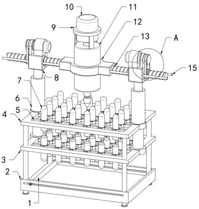
[0040] refer to Figure 1-7 , a precision mechanical workpiece punching device driven by electromagnetic force, including a top frame 4, two middle frames 3 and a bottom compartment 2 arranged sequentially at the bottom of the top frame 4, and two symmetrically arranged on both sides of the top of the top frame 4 The oil cylinder 6 and the bearing tube 11 vertically arranged at the top center of the top frame 4;

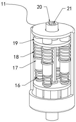
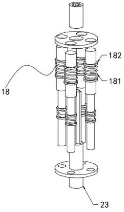
[0041] The top and bottom of the inner chamber of the carrying cylinder 11 are horizontally provided with built-in moving plates 19, and the bottom of the top built-in moving plates 19 is arranged in an annular array along the circumferential direction of the carrying cylinder 11. The sleeve 17 fixedly connected to the top of the inner cavity of the bearing cylinder 11, the top of the built-in moving plate 19 at the bottom is arranged in an annular array along the circumferential direction of the bearing cylinder 11. The bottom of the chamber is fixedly connected wi...

Embodiment 2

[0051] refer to Figure 1-7 , transmission structure 1 includes cross rod 1 241, transmission structure 2 includes cross rod 2 242, transmission structure 3 includes cross rod 3 243, one end of the output shaft of motor 10 is fixedly connected with the end of cross rod 1 241, and the drill bit One end of the butt joint rod 23 close to the connecting shaft 20 is fixedly connected to the end of the cross rod two 242, and the end of the drill bit near the drill bit docking rod 23 is fixedly connected to the end of the cross rod three 243. And the cross groove 21 that is compatible with the cross rod one 241 and the cross rod two 242, the end of the drill bit docking rod 23 near the drill bit is provided with the cross groove 21 that is compatible with the cross rod three 243, and the cross rod three 243 on the top of the drill bit One end of the drill bit is fixedly connected with a magnet piece, and the top of the inner cavity of the cross groove 21 at the end of the drill bit d...

Embodiment 3

[0053] refer to Figure 1-7 , one end of the collection rod 1 is connected with a moving column 27 through a rectangular rod 22, and one end of the moving column 27 is fixedly connected with a pull ring 28, and the other end of the collecting rod 1 is connected with a rectangular rod 22 through a moving column 27, and the rectangular rod 22 One end is fixedly connected with a pull ring 28, and the two side walls of the bottom bin 2 are provided with a rectangular groove 29 compatible with the rectangular rod 22, and a slope is provided on one side of the collecting rod 1. Specifically, it can be known from the above embodiments: The cooperation of collecting rod 1, rectangular rod 22, moving column 27 and pull ring 28, pulling pull ring 28 drives collecting rod 1 to move left and right, when two moving columns 27 are positioned in rectangular groove 29, collecting rod 1 can rotate, make The slope corresponds to the bottom of the inner cavity of the bottom bin 2, so that the co...


PUM


Abstract

The invention relates to the technical field of perforating machines, in particular to precise mechanical workpiece perforating equipment driven through electromagnetism, and solves the problems that in the prior art, in the operation process, lifting of a drill bit is rigid, the drill bit is fragile as precise perforating equipment, the perforating process is fine, and the perforating efficiency is high. And rigid movement directly causes the high error rate of punching and the high damage rate of a drill bit. The invention discloses precision type mechanical workpiece punching equipment driven by electromagnetism. The precision type mechanical workpiece punching equipment comprises a top frame, a middle frame, a bottom bin and two oil cylinders, wherein the middle frame and the bottom bin are sequentially arranged at the bottom of the top frame, and the two oil cylinders are symmetrically arranged on the two sides of the top of the top frame. According to the invention, a buffering effect can be achieved, rigid acting force is further buffered and converted into flexible acting force so as to adapt to punching operation of a precise workpiece, a drill bit is protected, meanwhile, the error rate and the damage rate of punching can be effectively reduced, and the production and processing quality can be improved.

Description

technical field [0001] The invention relates to the technical field of punching machines, in particular to an electromagnetically driven precision mechanical workpiece punching device. Background technique [0002] The punching machine is composed of four parts that cooperate with each other to complete the punching process. First, move the material to the scanning area of ​​the camera of the automatic punching machine. After the camera scans the image, it will process it and send a signal to the control part. After the control part receives the signal, it will further process and control the action of the transmission part, so that the punch is X on the plane. Axis, Y axis move, the pneumatic part starts to work after the movement is completed, and the solenoid valve controls the cylinder to perform the punching action. The automatic punching machine punches positioning holes, and the whole action is done in one go, fast, accurate and efficient. [0003] According to the ...

Claims


Application Information

Patent Timeline
Patent Type & Authority Applications(China)
IPC IPC(8): B23B39/00B23B47/00B23Q11/00
CPCB23B39/00B23B47/00B23Q11/0042
Inventor 钱士汪
Owner 常州亚迪机械有限公司
Why Eureka
Try Eureka