Load carrying platform shuttle

Active Publication Date: 2015-06-04
CONCRETE CANVAS TECH LTD
View PDF7 Cites 21 Cited by
  • Summary
  • Abstract
  • Description
  • Claims
  • Application Information

AI Technical Summary

Problems solved by technology

The lengthy time it takes to unload the deck, and its prolonged position outboard of the building under construction, means that other loading operations, including use of the crane for loading materials onto other levels, are restricted.
Crane hire is a major cost in multi-storey constr

Method used


Image

  • Load carrying platform shuttle
  • Load carrying platform shuttle
  • Load carrying platform shuttle

Examples


Example

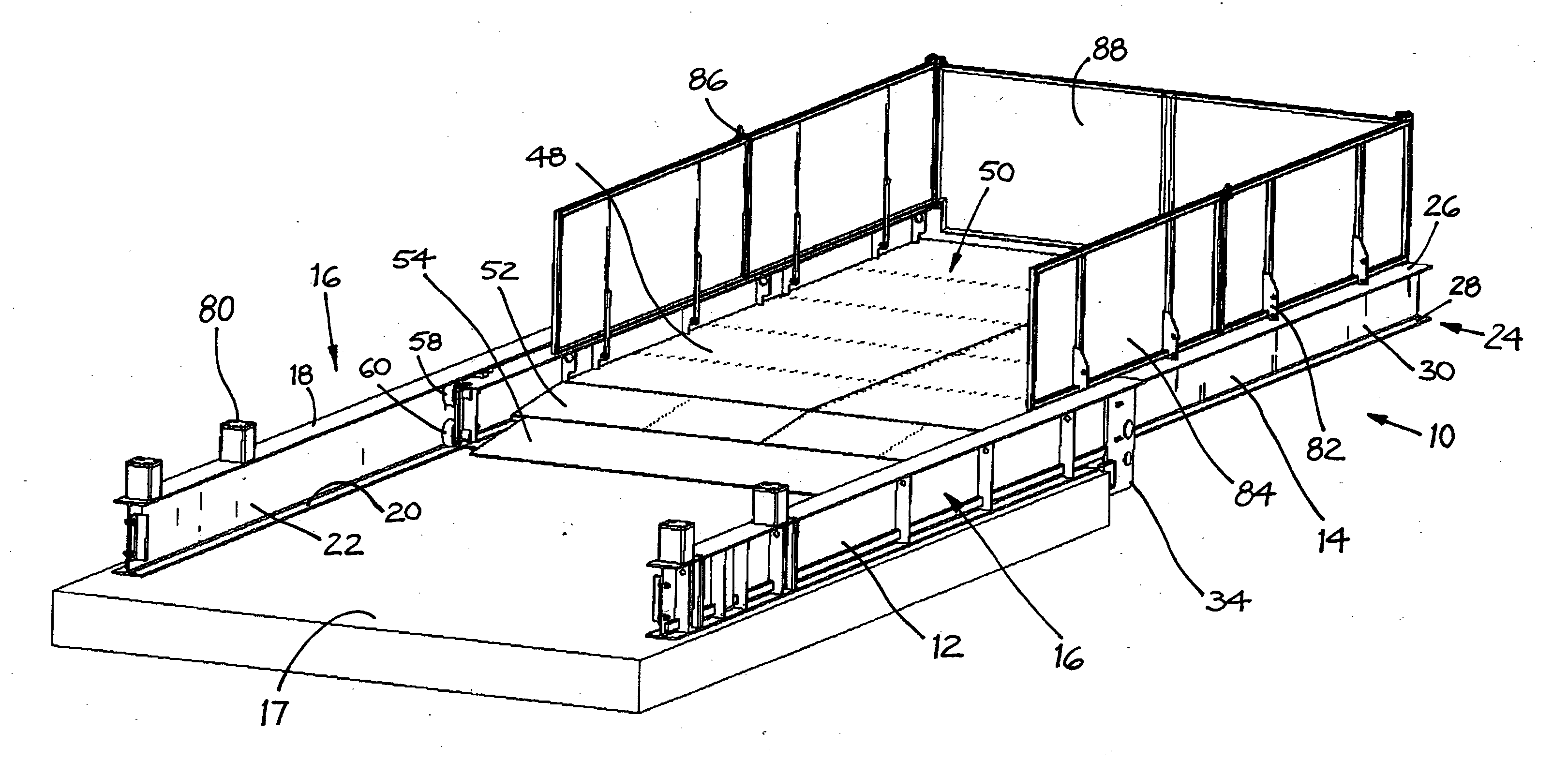
[0047]In the embodiments described below, like reference numerals refer to like features or components. Also, in some instances where there is a plurality of similar features or components positioned symmetrically, only some of the features or components may be labelled in the drawing figures. The embodiments are described in the context of the construction of multi-storey buildings, but the present invention is equally applicable to the transport industry or to the warehousing industry where heavy loads need to be moved into and out of a building.

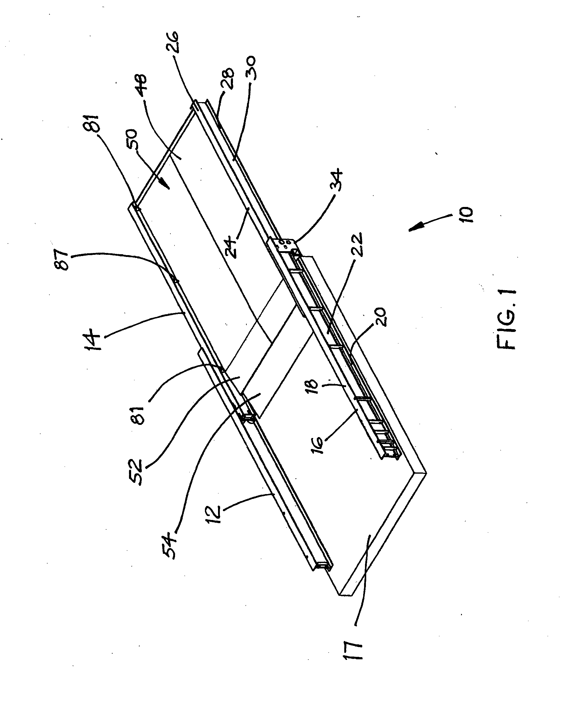
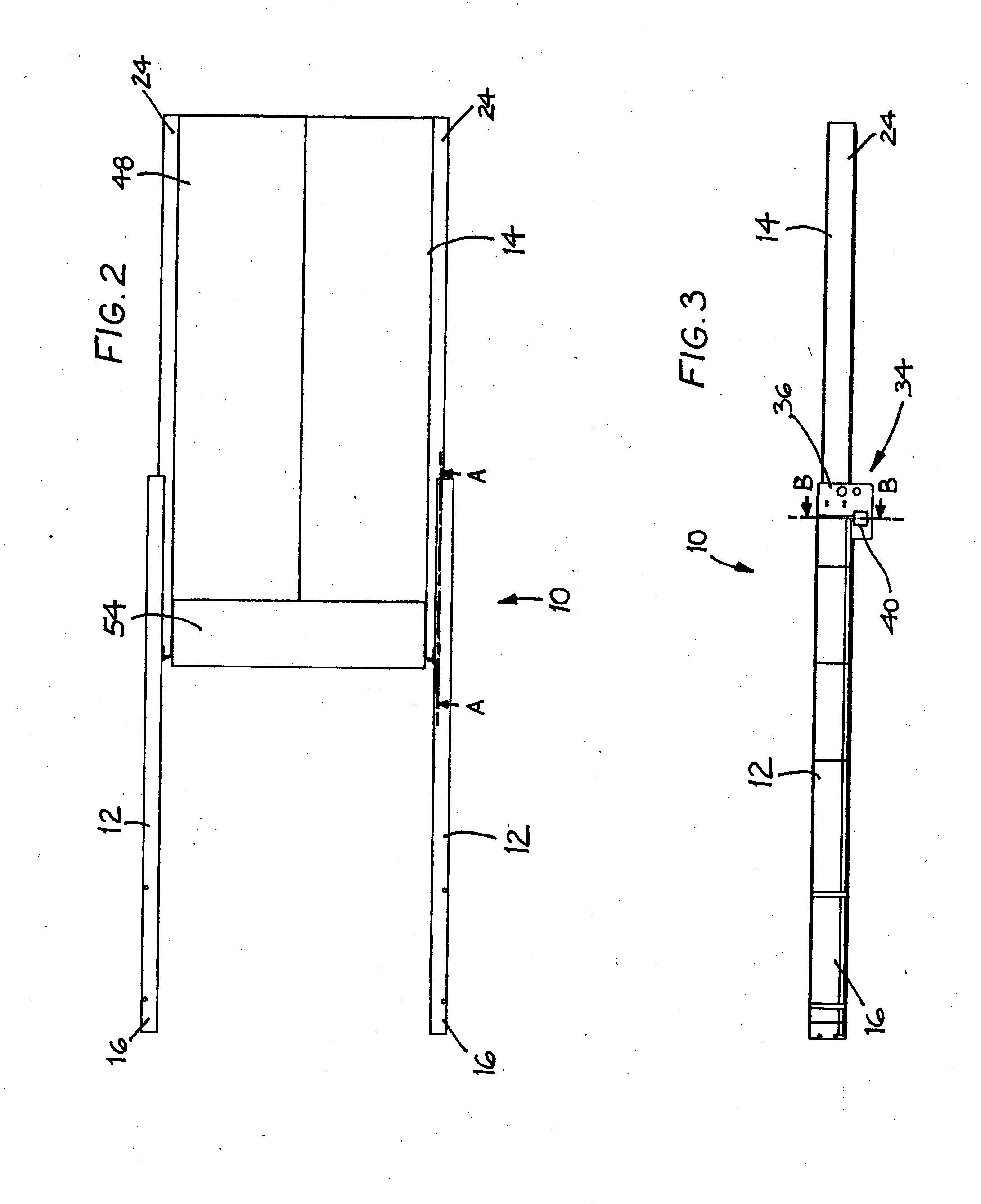
[0048]With reference to the embodiment shown in FIGS. 1 to 18, a load carrying platform shuttle 10 is shown in an extended configuration in FIGS. 1 to 6 and 14, and is shown in a retracted configuration in FIG. 15. The load shuttle 10 has two main components: a static frame 12 and a movable carriage 14. FIGS. 7 to 11 show the frame 12 in isolation and FIGS. 12 and 13 show the carriage 14 in isolation. The carriage 14 is nested within the f...


PUM


Abstract

A load carrying platform shuttle (10) has a static frame (12) and a movable carriage (14). The frame is securable to a mounting location, such as a given working level of a multi-storey building under construction, and the carriage is arranged to telescope into the static frame between an extended position outboard of the mounting location and a retracted position inboard of the mounting location. The movable carriage can move between the extended position and the retracted position while carrying a load. The shuttle includes a motor (76) and gear assembly (72, 74, 78) for driving the movement of the carriage between the extended position and the retracted position while carrying the load.

Description

FIELD OF THE INVENTION[0001]The present invention relates to a load carrying platform shuttle for use in a variety of commercial load carrying applications, such as in the construction of multi-storey buildings, in the warehousing industry and in the transport industry, where temporary or permanent use is required. The present invention also relates to a load carrying platform shuttle that embodies certain improvements over movable work platforms of the prior art.BACKGROUND[0002]Movable work platforms (also known as loading platforms, transportation platforms or construction platforms) are commonly used in multi-storey construction sites for the loading and unloading of building and other materials to and from a given working level of the building under construction. Such work platforms are secured within the building and can move between a retracted configuration and an extended configuration. In the extended configuration, the platform protrudes from the building and acts as a loa...

Claims


Application Information

Patent Timeline
IPC IPC(8): E04G21/16F16M11/18F16M11/04
CPCE04G21/166F16M11/18F16M11/048E04G5/001E04G3/28E04G3/18
Inventor MCKEON, ALLAN SYDNEY
Owner CONCRETE CANVAS TECH LTD
Why Eureka
Try Eureka