Wireless camera

a technology of wireless cameras and cameras, applied in the field of wireless cameras, can solve problems such as difficulty in ensuring transmission quality

Inactive Publication Date: 2006-04-18
SONY CORP
View PDF17 Cites 21 Cited by
  • Summary
  • Abstract
  • Description
  • Claims
  • Application Information

AI Technical Summary

Benefits of technology

[0005]Accordingly, the present invention has an object to overcome the above-mentioned drawbacks of the prior art by providing a wireless camera which can be operated by single operator with its mobility desirably secured.

Problems solved by technology

On the other hand, in a relay system employing such a wireless camera, it is difficult to secure transmission quality under the fading environment caused by movement and multipath.

Method used


Image

  • Wireless camera
  • Wireless camera
  • Wireless camera

Examples


Embodiment Construction

[0026]A ground digital radio relay system (referred to as a radio relay system, hereinafter) to perform a relaying from the spot for television broadcasting such as news programs, sports programs, and various event programs will further be described below concerning the best modes for carrying out the present invention with reference to the accompanying drawings.

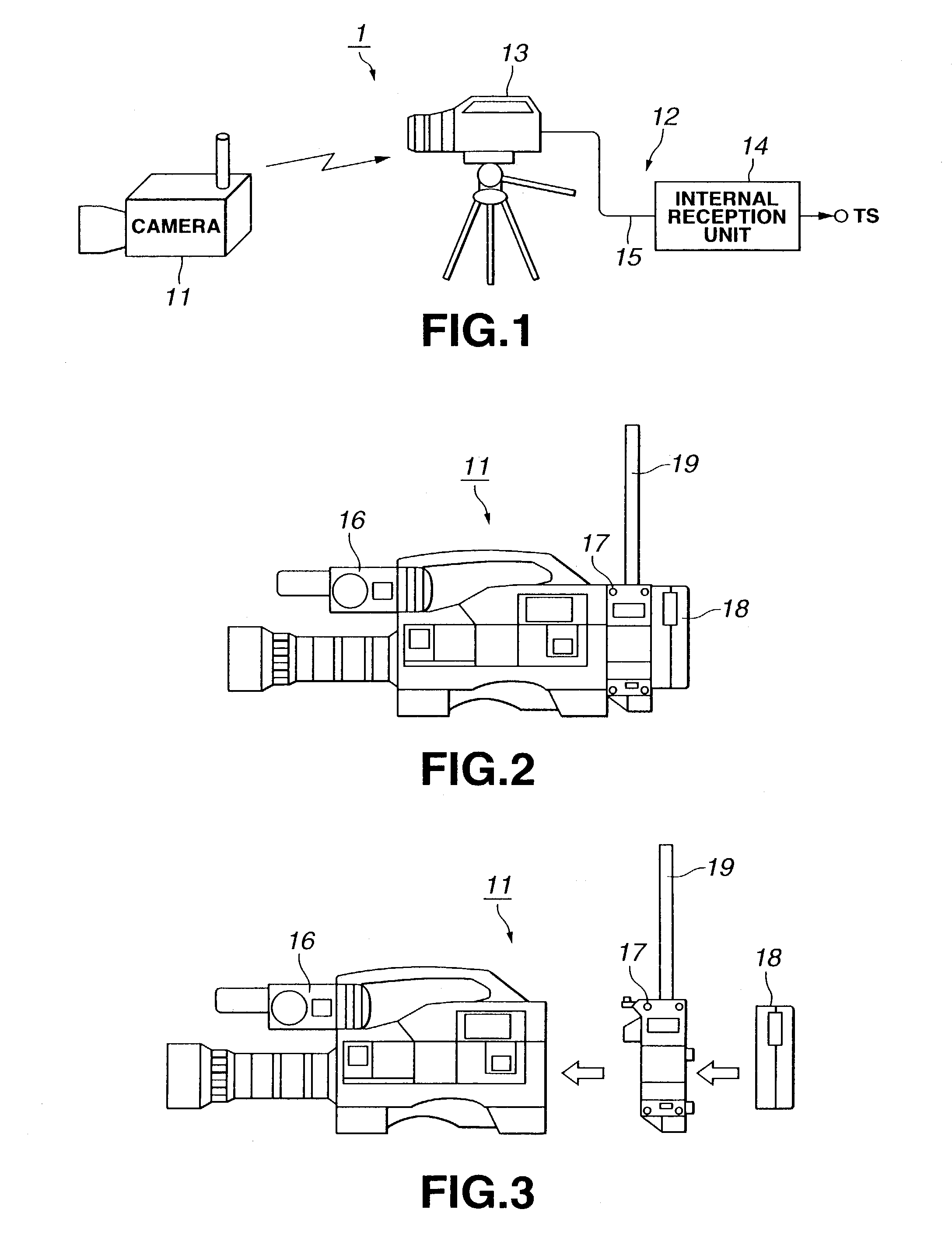
[0027]FIG. 1 shows the configuration of a radio relay system 1 according to the present invention.

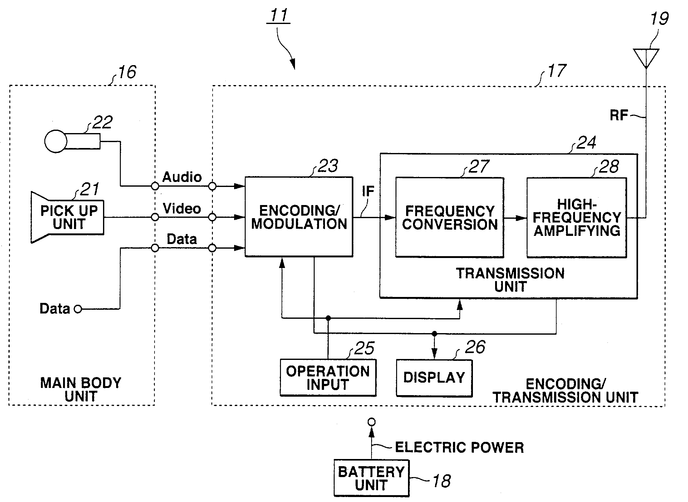
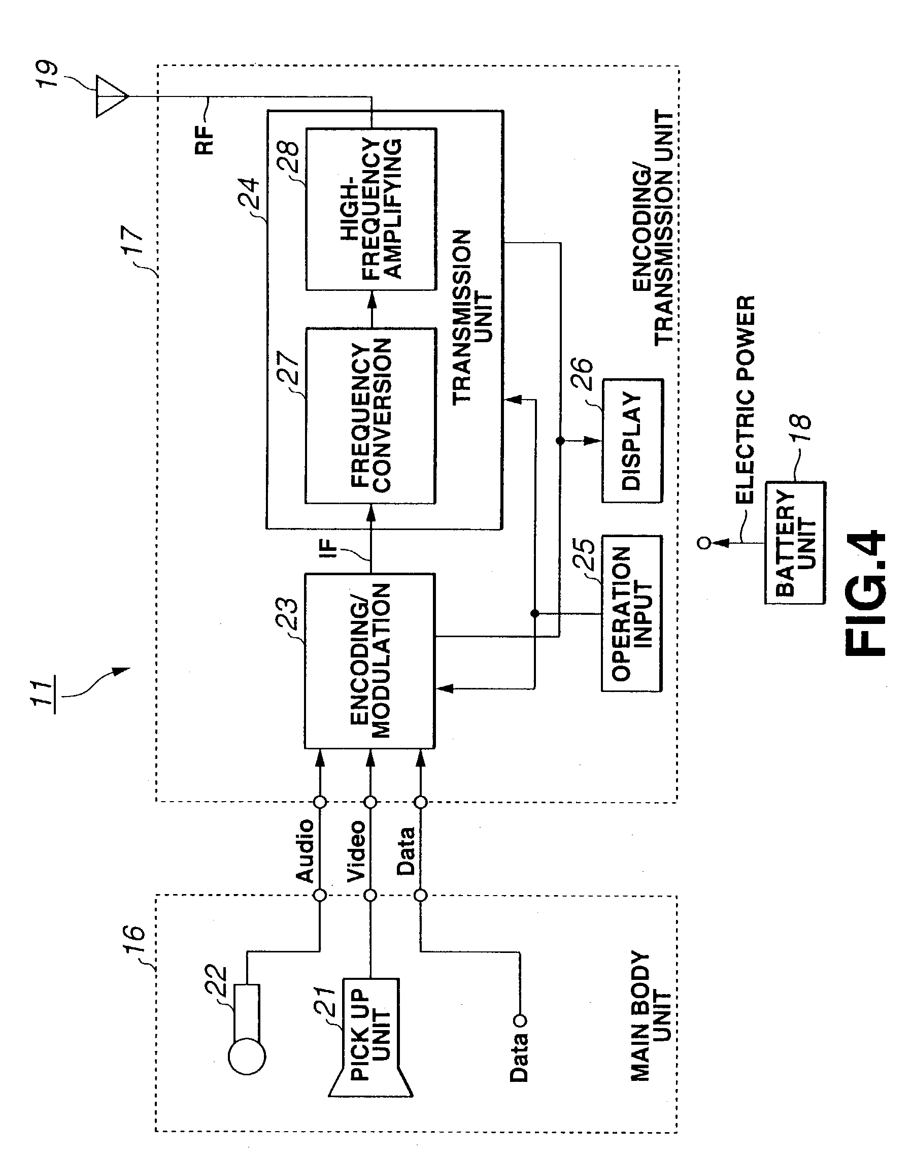
[0028]As shown in FIG. 1, the radio relay system 1 includes a wireless camera 11 for shooting a subject, a reception relay station 12 for receiving transmission signals from the wireless camera 11. The reception relay station 12 includes an external reception unit 13, an internal reception unit 14, and a plurality of IF cables 15 which connects the external reception unit 13 and the internal reception unit 14.

[0029]The radio relay system 1 is used to perform a relaying from the spot for television broadcasting such as news progr...


PUM


Abstract

A wireless camera 11 includes a main body unit 16, encoding / transmission unit 17, and a battery unit 18. The encoding / transmission unit 17 includes a encoding / modulation unit 23 for performing MPEG 2 encoding and OFDM modulation, frequency converter 27, high-frequency amplifier 28, and a transmission antenna 19. The main body unit 16, encoding / transmission unit 17, and battery unit 18 are unitedly configured.

Description

TECHNICAL FIELD[0001]The present invention relates to a wireless camera for use in a relaying from the spot for television broadcasting.BACKGROUND ART[0002]Conventionally, wireless cameras have been used to perform a relaying from the spot for television broadcasting such as news programs, sports programs, and various event programs. When such a wireless camera is used, video signals and audio signals picked up and gathered by the wireless camera are transmitted to a base relay station such as a relay car using ground waves employing radio transmission. Thus, when such a wireless camera is used, since it is not necessary to take time to arrange and remove cables, less labor is required as compared with a conventional camera which is connected to cables. Also, since the camera angle is spread and degree of freedom is increased, the mobility of a wireless camera is improved at the spot where a relaying for television broadcasting is performed.[0003]Recently, in transmitting video sign...

Claims


Application Information

Patent Timeline
Patent Type & Authority Patents(United States)
IPC IPC(8): H04N5/232H04L27/26H04N5/225
CPCH04L27/2601H04N5/23203H04N5/2252H04N23/51H04N23/66
Inventor ISHIZAKA, KAZUOKOSUGI, HIROSHI
Owner SONY CORP
Why Eureka
Try Eureka