
Liquid heater

A technology for liquid heaters and heating components, which is applied to cooking utensils, water boiling appliances, household appliances, etc. It can solve the problems of small clamping force of the inner tank, affecting the use of the liquid heater, and falling out of the base shell, etc., to avoid Damage, reduce the possible effects of rusting electrical connections in humid environments

Pending Publication Date: 2020-10-09
JOYOUNG CO LTD
View PDF9 Cites 0 Cited by
  • Summary
  • Abstract
  • Description
  • Claims
  • Application Information

AI Technical Summary

Problems solved by technology

If the rate of change of the width of the liner with the height decreases is small, or even does not change, the inclination angle of the liner is small, and the difference between the inner diameter of the shell and the outer diameter of the base is small. When the liner is folded, the liner is folded It is clamped between the inner wall of the shell and the outer wall of the base, and the clamping force is too large, so that the base cannot be pulled out from the shell, and the liner cannot fall off the folded state, which will affect the next use of the liquid heater
[0005] If the change rate of the width of the liner decreases as the height decreases, the inclination angle of the liner is relatively large, and the difference between the inner diameter of the shell and the outer diameter of the base is large. When the liner is folded, the liner is located between the shell and the base. The clamping force of the shell and the base on the liner is small, and even the inner wall of the shell and the outer wall of the base are not in direct contact with the liner, causing the base to fall out of the shell easily
When moving the folded liquid heater, the base is easy to fall out of the shell under the action of gravity, requiring the user to refold the inner tank, which is troublesome and poor user experience

Method used


Image

  • Liquid heater
  • Liquid heater
  • Liquid heater

Examples


Embodiment Construction

[0032] The present invention will be described in further detail below in conjunction with the accompanying drawings.

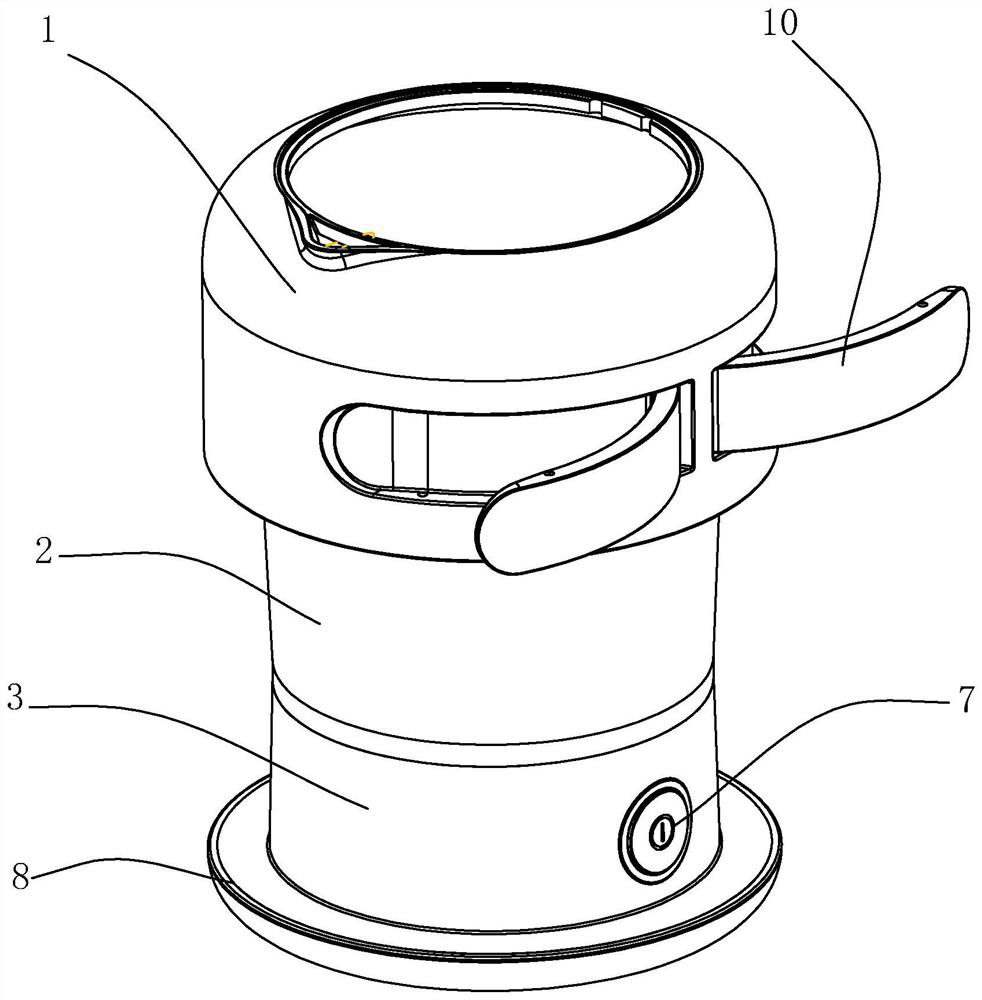
[0033] see figure 1 , a liquid heater, including a shell assembly 1, a foldable inner tank 2, and a base assembly 3 connected in sequence.

[0034] In this embodiment, the housing component 1 is provided with a handle 10, and the handle 10 is rotatably connected to the outer wall of the housing. The handle 10 can be embedded in the depression on the outer wall of the shell assembly 1, so that the appearance of the product is better, and the space occupied by the liquid heater is reduced, and the portability experience is better.

[0035] In other embodiments, the outer wall of the housing assembly 1 is a smooth surface, and the handle 10 is not provided.

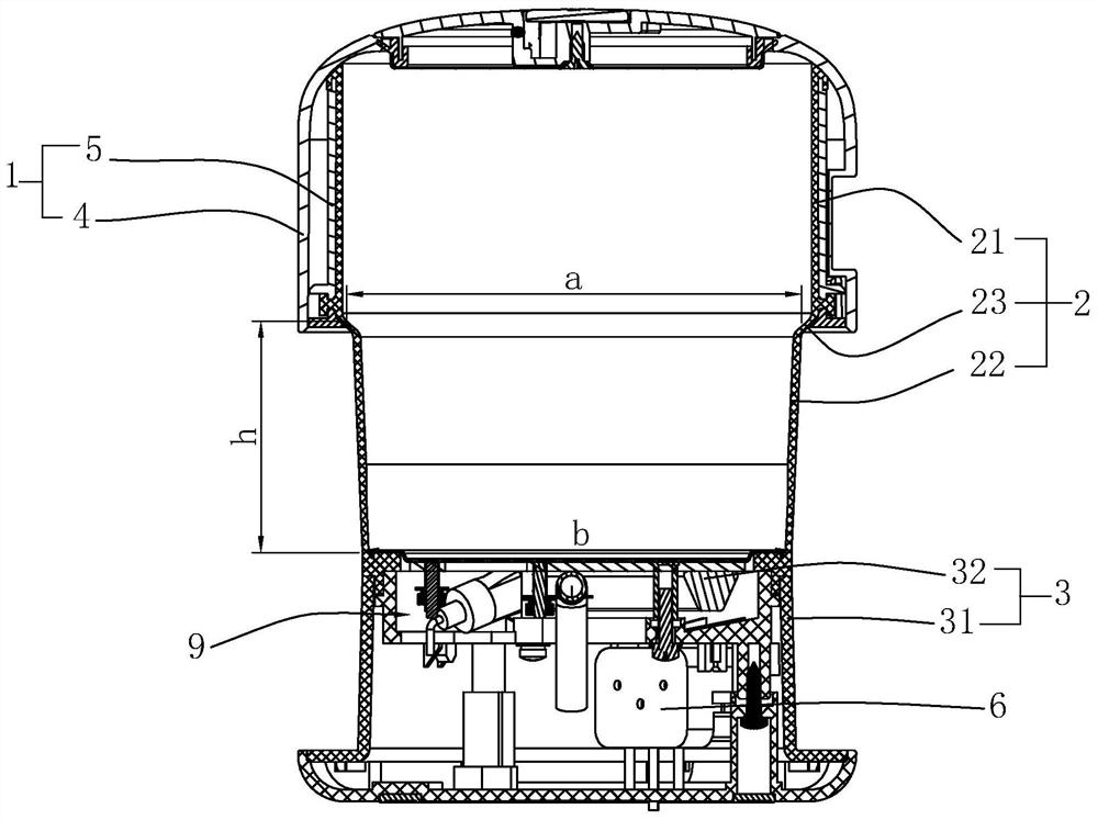
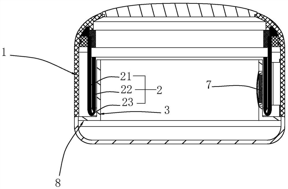
[0036] see figure 2 with image 3 , In this embodiment, the liner 2 includes an upper portion 21 of the liner, a bent portion 23 and a lower portion 22 of the liner. The liner 2 is integrally molded w...


PUM


Abstract

The invention discloses a liquid heater. The liquid heater comprises a shell assembly, a foldable inner container and a base assembly. The inner container comprises an inner container upper portion connected into the shell assembly, an inner container lower portion capable of being folded into the shell assembly and connected with the base assembly, and a bent portion connected with the inner container upper portion and the inner container lower portion. The width of any height of the bent part is a, the height from the bent part to the bottom end of the lower portion of the inner container ish, the bottom end of the lower portion of the inner container is used for being connected with the base assembly, the width is b, all parameters meet 1.86<=(a-b) / h<28.6, and when the inner containeris folded, the base assembly is sleeved with the shell and hidden between the shell assembly; when the inner container is not folded, the lower portion of the inner container is exposed out of the shell assembly.

Description

technical field [0001] The invention relates to the field of household appliances, in particular to a liquid heater. Background technique [0002] A liquid heater is a device for heating liquids, including electric kettles, soybean milk machines and cooking machines. [0003] The existing foldable electric kettle comprises a shell, a foldable liner and a base. The shell is fixed to the upper end of the inner tank, and the lower end of the inner tank is fixed to the base. After the body of the kettle is folded, the shell is covered outside the base, and the inner liner is located between the shell and the base. Therefore, the inner diameter of the housing must be larger than the outer diameter of the base. The width of the top of the liner is close to the width of the inner diameter of the shell, and the width of the bottom of the liner is close to the width of the outer diameter of the base. [0004] The width of the liner gradually decreases from top to bottom, that is,...

Claims


Application Information

Patent Timeline
Patent Type & Authority Applications(China)
IPC IPC(8): A47J27/21
CPCA47J27/21041A47J27/21166
Inventor 朱泽春孙立刚
Owner JOYOUNG CO LTD
Learn More