
A Practical Ventilation Method for Factory Buildings

A plant and practical technology, applied in applications, heating methods, household appliances, etc., can solve problems such as large deviations in calculation results, and achieve the effect of improving production quality and working environment.

Active Publication Date: 2017-12-22
哈尔滨新海德智能环境工程有限公司
View PDF3 Cites 0 Cited by
  • Summary
  • Abstract
  • Description
  • Claims
  • Application Information

AI Technical Summary

Problems solved by technology

[0002] In the overall factory building exhaust gas treatment technology, the calculation of the number of air changes is necessary. The existing number of air changes takes the volume of the factory building as the only base, resulting in a large deviation in the calculation results in practical applications. This invention aims to solve this problem

Method used


Image

  • A Practical Ventilation Method for Factory Buildings

Examples


Embodiment Construction

[0025] The following will clearly and completely describe the technical solutions in the embodiments of the present invention with reference to the accompanying drawings in the embodiments of the present invention. Obviously, the described embodiments are only some, not all, embodiments of the present invention. Based on the embodiments of the present invention, all other embodiments obtained by persons of ordinary skill in the art without making creative efforts belong to the protection scope of the present invention.

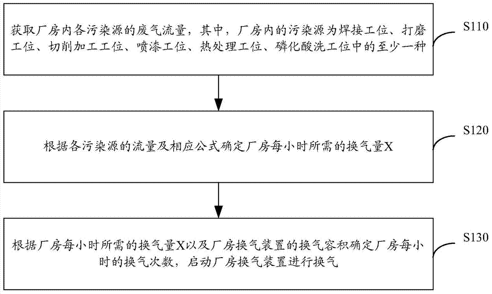
[0026] figure 1 It is a flow chart of a practical plant ventilation method according to an embodiment of the present invention. As shown in the figure, the plant ventilation method includes the following steps:

[0027] S102. Obtain the exhaust gas flow rate of each pollution source in the factory building. The pollution sources in the factory building are welding stations, grinding stations, cutting processing stations, painting stations, heat treatment stat...


PUM


Abstract

The invention discloses a practical ventilation method for a plant building. The method comprises the steps of acquiring waste gas flow rate of each pollution source in the plant building, wherein the pollution source in the plant buildings includes at least one of a welding station, a grinding station, a cutting processing station, a painting station, a thermal treating station and a phosphoric acid pickling station; determining the ventilation quantity X per hour of the plant building by the formula of X=k(Q+nP) if each pollution source has the same flow rate, wherein Q is the volume of the plant building, n is the quantity of the pollution sources, P is the waste gas flow rate of each pollution source, and k is the air leakage coefficient of the plant building and ranges from 1 to 1.5; determining the ventilation times per hour of the plant building according to the required ventilation quantity X per hour of the plant building and the ventilation volume of a ventilation device of the plant building; starting the ventilation device of the plant building to ventilate according to the determined ventilation times.

Description

technical field [0001] The invention relates to the field of environmental protection, in particular to a practical ventilation method for factory buildings. Background technique [0002] In the overall factory building exhaust gas treatment technology, the calculation of the number of air changes is necessary. The existing number of air changes takes the volume of the factory building as the only base, resulting in a large deviation in the calculation results in practical applications. The present invention aims to solve this problem. Contents of the invention [0003] The invention provides a practical factory building ventilation method, which is used to better realize the exhaust gas treatment of the whole factory building. [0004] In order to achieve the above object, the present invention provides a practical plant ventilation method, comprising: [0005] Obtain the exhaust gas flow rate of each pollution source in the factory building, wherein the pollution source...

Claims


Application Information

Patent Timeline
Patent Type & Authority Patents(China)
IPC IPC(8): F24F7/08F24F11/02
CPCF24F7/08F24F11/30F24F2110/00
Inventor 葛维翰孙振伟
Owner 哈尔滨新海德智能环境工程有限公司
Learn More