Crystal head buckling device

A buckle device and crystal head technology, which is applied to coupling devices, parts of connection devices, network connectors, etc., can solve problems such as unusable crystal heads, fragile snap parts, and no protective structure.

Inactive Publication Date: 2015-07-08
WARECONN TECH SERVICE (TIANJIN) CO LTD
View PDF8 Cites 4 Cited by
  • Summary
  • Abstract
  • Description
  • Claims
  • Application Information

AI Technical Summary

Problems solved by technology

The existing crystal head is integrally formed. The buckle of the crystal head is relatively fragile and easy to break without a protective

Method used


Image

  • Crystal head buckling device
  • Crystal head buckling device
  • Crystal head buckling device

Examples


Embodiment Construction

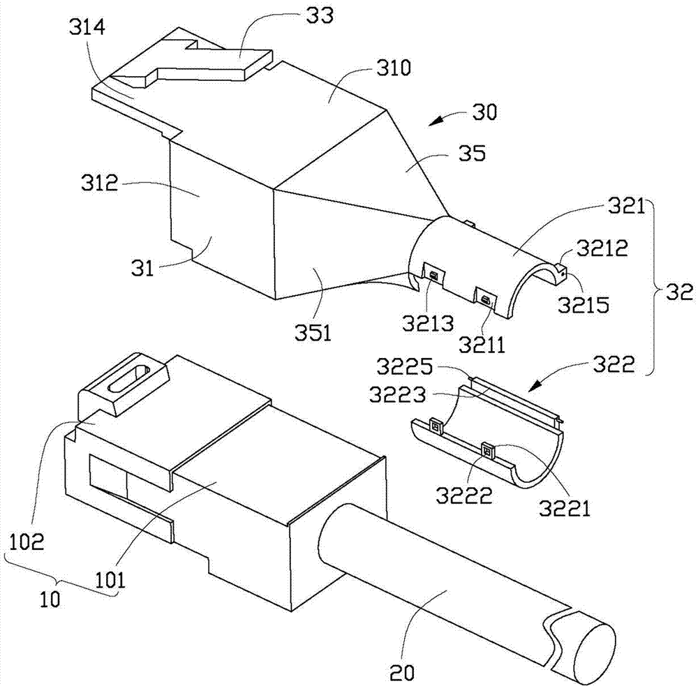
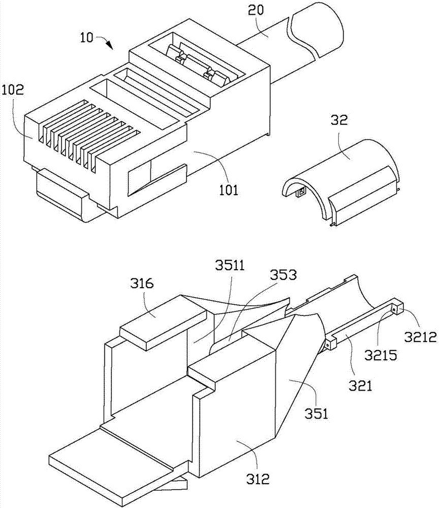
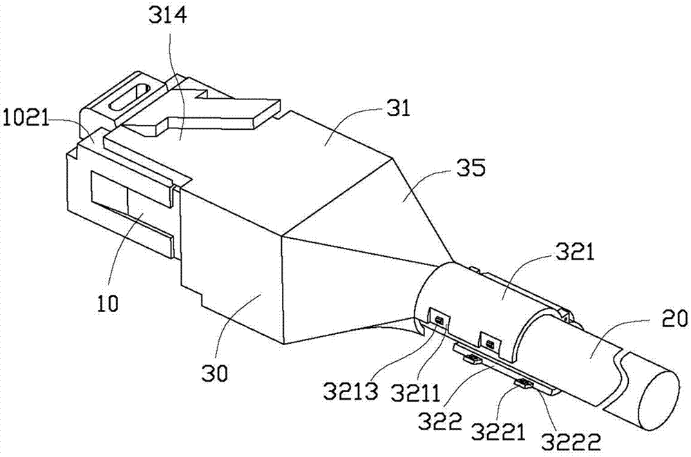
[0013] see figure 1 and figure 2 , a preferred embodiment of the crystal head buckle device of the present invention is detachably installed on the crystal head body 10 . In this embodiment, the crystal head body 10 may be a crystal head with a buckle broken.

[0014] The crystal head body 10 includes a base portion 101 and a joint portion 102 set on one end of the base portion 101 and capable of being plugged into an interface of an electronic device. The other end of the base part 101 is connected to the cable 20 .

[0015] The crystal plug locking device 30 includes a main body 31 , a wire clip 32 and a connecting portion 35 connecting the main body 31 and the wire clip 32 .

[0016] The main body 31 includes a top plate 310, two side plates 312 extending vertically downward from both sides of the top plate 310, two bottom plates 316 extending from the bottom of the two side plates 312, and an end away from the top plate 310 from the wire clip 32. Extended extension pl...


PUM


Abstract

A crystal head buckling device is detachably installed on a crystal head body of which one end is connected with a cable. The crystal head buckling device comprises a body part clamped to the crystal head body, and a wire clamp. The body part is provided with a buckling part. The wire clamp clamps the cable of the crystal head body. The crystal head buckling device is detachably installed on the crystal head body, which facilitates replacement of a damaged buckle and avoids the situation in which a crystal head cannot be used due to damage to a buckle.

Description

technical field [0001] The invention relates to a crystal head buckle device. Background technique [0002] Telephone lines or network cables often use crystal plugs to plug into the sockets of terminal electronic equipment for communication. The existing crystal head is integrally formed, and the buckle parts of the crystal head are relatively fragile and easy to break without a protective structure. Frequent plugging and unplugging of the crystal head may easily damage the buckle parts, thus making the crystal head unusable. Contents of the invention [0003] In view of the above, it is necessary to provide a replaceable crystal head buckle device. [0004] A crystal head buckle device, which is detachably installed on the crystal head body, one end of the crystal head body is connected with a cable, the buckle device includes a main body and a wire clip that are engaged with the crystal head body, the main body There is a buckle part on the top, and the cable clamp cl...

Claims


Application Information

Patent Timeline
IPC IPC(8): H01R13/639
CPCH01R13/6275H01R2201/04H01R2201/16
Inventor 刘磊
Owner WARECONN TECH SERVICE (TIANJIN) CO LTD
Why Eureka
Try Eureka