Thermal storage control system and thermal storage body used in same

A control system and heat storage body technology, applied in heating systems, hot air central heating systems, heat storage equipment, etc., can solve the problems of difficult indoor space heating, low heat, etc., and achieve the effect of high-efficiency temperature control

Inactive Publication Date: 2015-07-08
PANASONIC INTELLECTUAL PROPERTY MANAGEMENT CO LTD
View PDF5 Cites 2 Cited by
  • Summary
  • Abstract
  • Description
  • Claims
  • Application Information

AI Technical Summary

Problems solved by technology

However, even if the heat stored in the low-temperature heat storage body is recovered, it is difficult to effectively heat the indoor space due to the small amount of recoverable heat.

Method used


Image

  • Thermal storage control system and thermal storage body used in same
  • Thermal storage control system and thermal storage body used in same
  • Thermal storage control system and thermal storage body used in same

Examples


Embodiment 1

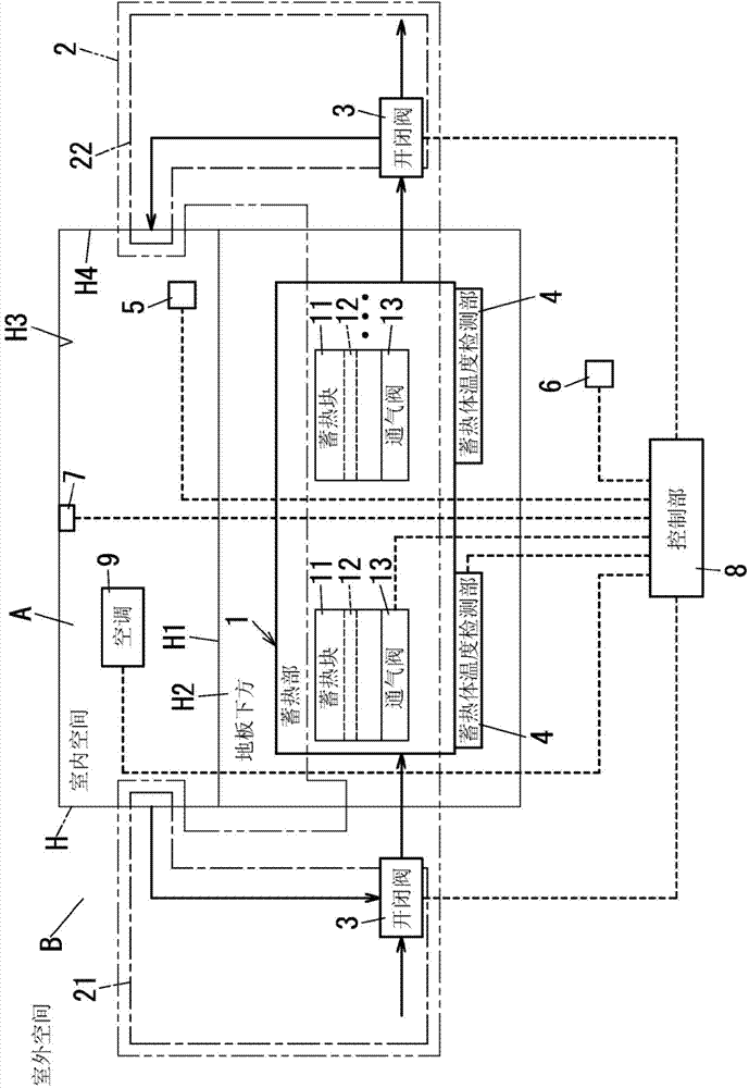
[0027] Such as figure 1 As shown, the heat storage control system of this embodiment controls the warm environment of the indoor space A in the building H, and includes a heat storage part 1, a ventilation passage 2, a plurality of on-off valves 3 (opening and closing members), a plurality of Thermal storage body temperature detection part 4 , indoor temperature detection part 5 , outdoor temperature detection part 6 , human detection part 7 and control part 8 .

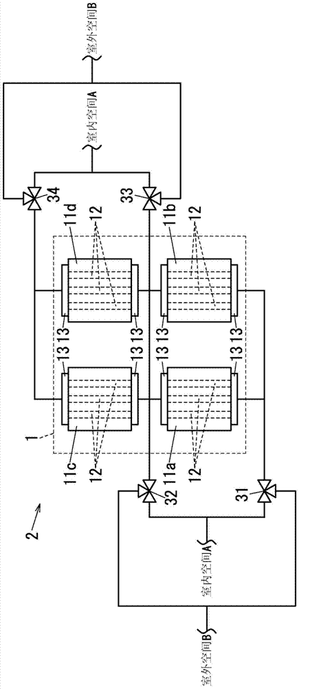
[0028] The heat storage unit 1 includes a plurality of heat storage blocks 11 (heat storage bodies), and the plurality of heat storage blocks 11 are arranged in a space H2 under the floor of the building H along a floor surface H1 (constituting surface). In this example, if figure 2 As shown, four thermal storage blocks 11a-11d which are some thermal storage blocks 11 are arrange|positioned in 2 rows x 2 columns along the floor surface H1. Note that in distinguishing the four thermal storage blocks 11, each therma...

Embodiment 2

[0100] The heat storage control system of this embodiment has Figure 5 Vent path 2 of the structure shown. The same reference numerals are assigned to the same constituent elements as those of the first embodiment, and explanations for these constituent elements will be omitted.

[0101] The plurality of thermal storage blocks 110 a to 110 d constituting the ventilation passage 2 of the present embodiment are the thermal storage blocks 11 without the ventilation valve 13 . In addition, in Figure 5 Among them, six on-off valves 111 to 114, 121, and 122 are connected to four thermal storage blocks 110a to 110d arranged in 2 rows×2 columns. Note that the on-off valves 111 to 114 are formed using two-way valves, and the on-off valves 121 and 122 are formed using three-way valves.

[0102] The output of the on-off valve 111 is connected to the inflow ports of the respective air holes 12 of the heat storage blocks 110a and 110b, and the output of the on-off valve 112 is connect...


PUM


Abstract

This thermal storage control system is provided with a plurality of thermal storage bodies (thermal storage blocks (11)), a ventilation pathway (2), a plurality of opening / closing members (on-off valve (3), blower valve (13)), and a control unit (8). The plurality of thermal storage bodies are each provided with a ventilation hole (12). The ventilation pathway (2) is formed containing the ventilation holes (12), and has a plurality of pathways extending from a first end to a second end in a manner so that air flows from the first end towards the second end. The plurality of opening / closing members open / close the ventilation pathway (2). The control unit (8) controls the opening / closing of the plurality of opening / closing members individually. The control unit (8) switches the pathway through which interior air flows in the ventilation pathway (2) by means of controlling the opening / closing of the plurality of opening / closing members individually on the basis of the temperature of an indoor space (A) and the temperature of each of the plurality of thermal storage bodies.

Description

technical field [0001] The present invention relates to a thermal storage control system and a thermal storage body used in the thermal storage control system. Background technique [0002] There is a system for reducing air-conditioning load by storing heat in a heat storage body arranged in a building and recovering the heat stored in the heat storage body using indoor air as a heat medium during an air-conditioning load usage period. For example, heating or cooling air is sent to a heat storage body under the floor of a building, heat is stored in the heat storage body by heat exchange, the heat stored in the heat storage body is recovered using indoor air as a heat medium, and then The air under the floor is returned to the indoor space via an on-off valve (damper) provided in the floor (for example, see Japanese Laid-Open Patent Publication No. 05-98718). [0003] In addition, there is a heat storage body constituted by arranging cement boards having vent holes side by...

Claims


Application Information

Patent Timeline
Patent Type & Authority Applications(China)
IPC IPC(8): F28D20/00E04B1/76
CPCF28F27/02Y02E60/142F28D20/0056F28D2020/0069F24F5/0017F24D5/02F24D19/1084F24D2220/006F24D11/006Y02E60/14F28D20/00
Inventor 室直树薮之内伸晃高桥勇人
Owner PANASONIC INTELLECTUAL PROPERTY MANAGEMENT CO LTD
Why Eureka
Try Eureka