Supercharge Your Innovation With Domain-Expert AI Agents!

ratchet connector

A ratchet and ratchet technology, which is applied in the direction of wrenches, screwdrivers, manufacturing tools, etc., can solve the problems that the clamping block is prone to chipped or slipped teeth, and cannot be stably pulled in one direction.

Active Publication Date: 2017-05-10
FUKUI TOOL CO LTD
View PDF6 Cites 0 Cited by
  • Summary
  • Abstract
  • Description
  • Claims
  • Application Information

AI Technical Summary

Problems solved by technology

It is not difficult to find that there are some deficiencies in the above-mentioned existing structure in detail. The main reasons are summarized as follows: one side of the locking block is provided with two slopes to fit in the cutting groove left or right, and the locking block The outer arc surface on the other side is continuously provided with a plurality of external ratchets to form a positive or reverse one-way engagement with the internal ratchets of the joint. Since the locking block is movable and slides in the slot, the When subjected to a large torsional force, the clamping block is prone to chipped or slipped teeth, making it impossible to pull stably in one direction

Method used


Image

  • ratchet connector
  • ratchet connector
  • ratchet connector

Examples


Embodiment Construction

[0052] In order to make the object, technical solution and advantages of the present invention clearer, the present invention will be described in further detail below in conjunction with specific embodiments and with reference to the accompanying drawings.

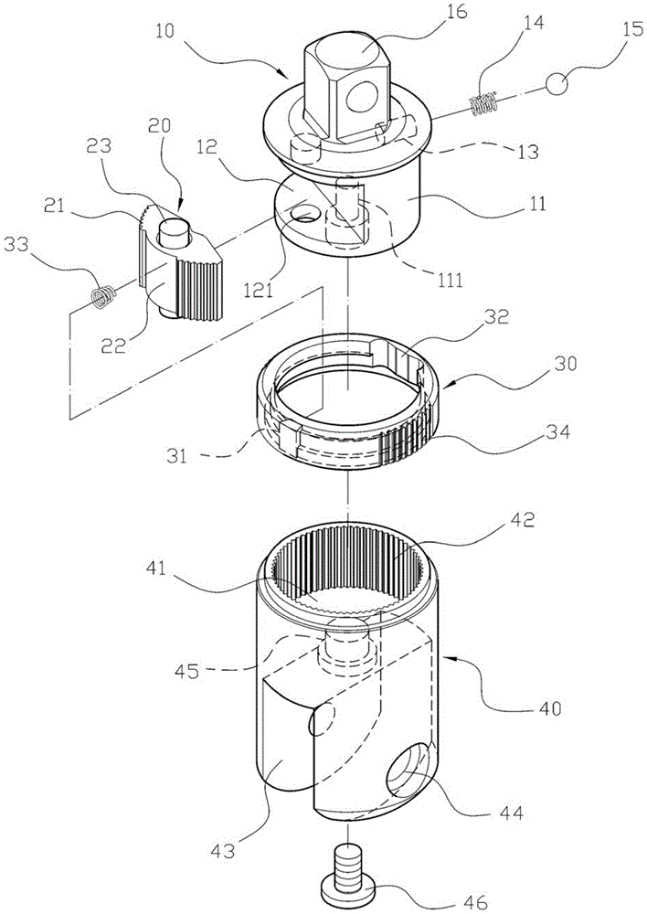
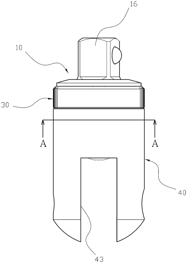
[0053] Please refer to figure 1 and figure 2As shown, a ratchet joint includes: a first body 10, a ratchet 20, a control ring 30 and a second body 40, a first body 10 forms a cylinder 11 at one end, the first body 10. A threaded hole 111 is provided on the top surface of the cylinder 11, and a semicircular groove 12 is provided on the peripheral surface of the cylinder 11, and the cylinder 11 is provided with a shaft hole 121 at the coaxial semicircular groove 12, and the cylinder 11 is provided with a perforation 13 on one side opposite to the semicircular groove 12, and a spring 14 and a ball 15 are sequentially placed in the perforation 13, and the first body 10 is formed with a polygonal rod 16 at the other end of t...


PUM


Abstract

The invention discloses a ratchet wheel joint. The ratchet wheel joint comprises a first body, wherein a cylinder is formed at one end of the first body, and is provided with a semicircular groove; the cylinder is provided with a shaft hole in the semicircular groove; tooth parts are respectively formed at the two sides of a ratchet; a slip surface is formed between the tooth parts; a shaft rod penetrates through the ratchet; the ratchet penetrates to the shaft hole by the shaft rod, and is pivoted in the semicircular groove; a fixed groove and a switching groove are symmetrically formed in the inner edge of a control ring; the control ring coats the cylinder, and touches a rolling ball by the switching groove; an elastic piece is arranged in the fixed groove, and is ejected on the slip surface; an accommodating chamber is formed in a second body, and is formed with a ring tooth part; and the second body coats the cylinder by the accommodating chamber, so that the ring tooth part can be engaged to the tooth parts of the ratchet to improve the greatest bearing torsion without generating the condition of tooth collapse or tooth slip.

Description

technical field [0001] The invention relates to a ratchet device, in particular to a ratchet joint capable of withstanding relatively large torque and easy to assemble. Background technique [0002] An existing ratchet mechanism, such as the "Ratchet Drive Mechanism" with the announcement certificate No. 369979 authorized on September 11, 1988, discloses a ratchet screwdriver with a lateral rotation control reversing function, which includes: A body, one end of which has a circular pivot seat, one side of the peripheral edge of the pivot seat has a stopper, and the other side of the pivot seat has two slots that are hollowed out to the outside, and the two slots are One pawl is respectively inserted, and the two pawls are respectively pushed outward by a spring provided in the slot; one adjustment ring is sleeved on the outside of the pivot seat of the body, and the inner edge side of the adjustment ring has a It is used to clamp the card slot of the block body, and the inn...

Claims


Application Information

Patent Timeline
Patent Type & Authority Patents(China)
IPC IPC(8): B25B23/00B25B13/46B25B15/04
CPCB25B13/465B25B15/04
Inventor 王键岡
Owner FUKUI TOOL CO LTD
Features
  • R&D
  • Intellectual Property
  • Life Sciences
  • Materials
  • Tech Scout
  • Unparalleled Data Quality
  • Higher Quality Content
  • 60% Fewer Hallucinations
Learn More