
A winding device capable of realizing fixed-point cutting on the winding core

A technology of winding device and fixed-point cutting, which is applied in the direction of winding strip, transportation and packaging, thin material processing, etc. The effect of preventing wrinkles, reducing waste, ensuring quality and efficiency

Active Publication Date: 2018-07-13
SHANGHAI LANQING INNOVATIVE MATERIAL & TECH CO LTD
View PDF7 Cites 0 Cited by
  • Summary
  • Abstract
  • Description
  • Claims
  • Application Information

AI Technical Summary

Problems solved by technology

At present, in the film winding process, there are usually multiple winding stations on one winding frame, that is, corresponding to multiple winding shafts; the winding device in the prior art, when changing rolls at multiple stations, different stations When the rewinding shaft is connected to the film, it cannot be connected to the designated position on the surface of the die (that is, the location where the adhesive strip is set); this will easily lead to unevenness of the rewinding joint, which will cause wrinkles on the film after rewinding, which will affect the quality of the product. , and there will be a lot of waste generated

Method used


Image

  • A winding device capable of realizing fixed-point cutting on the winding core
  • A winding device capable of realizing fixed-point cutting on the winding core
  • A winding device capable of realizing fixed-point cutting on the winding core

Examples


Embodiment Construction

[0036] The invention will be described in more detail hereinafter with reference to the accompanying drawings showing embodiments of the invention. However, this invention may be embodied in many different forms and should not be construed as limited to the embodiments set forth herein. Rather, these embodiments are provided so that this disclosure will be thorough and complete, and will fully convey the scope of the invention to those skilled in the art. In these drawings, the size and relative sizes of layers and regions may be exaggerated for clarity.

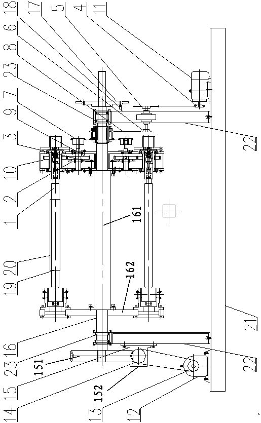
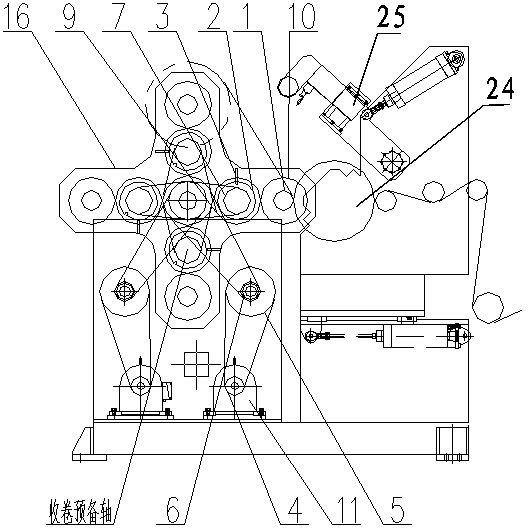
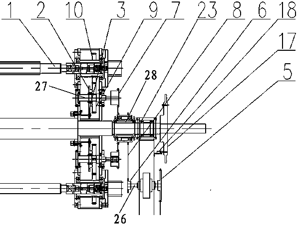
[0037] refer to Figure 1-3 , the present invention provides a winding device capable of realizing fixed-point cutting on the winding core, which includes a base and a winding frame (16) arranged on the base, used for film and other products on the friction roller (24) Winding to the winding shaft of the winding stand (16); the present invention can ensure that the winding shafts of different stations can be connected at t...


PUM


Abstract

The invention provides a rolling device capable of realizing fixed-point cutting on a roll core. The rolling device comprises a substrate and a rolling frame, wherein the rolling frame comprises a main shaft and a plurality of rolling shafts; the rolling shafts are evenly distributed around the circumference of the main shaft; two ends of each rolling shaft are respectively fixedly connected with the main shaft by two side plates; the rolling shafts rotate relative to the side plates; two ends of the main shaft are rotatably installed on the substrate; each rolling shaft is axially provided with a sticking strip. The rolling device also comprises a first power mechanism and a second power mechanism, wherein the first power mechanism drives the main shaft to rotate, and the second power mechanism drives the rolling shafts to rotate. The rolling device also comprises a first control mechanism and a second control mechanism, wherein the first control mechanism is used for controlling the rolling frame to stop rotating when each rolling shaft on the rolling frame rotates to a working station on which a friction roll is positioned; the second control mechanism is used for controlling the rolling shafts to stop rotating when the sticking strips on the rolling shafts rotate to a film joint position on the friction roll.

Description

technical field [0001] The invention relates to the technical field of design of a winding device, in particular to a winding device capable of realizing fixed-point cutting on a winding core. Background technique [0002] Film winders are an essential part of the film production process, and there are various types of film winders. At present, in the film winding process, there are usually multiple winding stations on one winding frame, that is, corresponding to multiple winding shafts; the winding device in the prior art, when changing rolls at multiple stations, different stations When the rewinding shaft is connected to the film, it cannot be connected to the designated position on the surface of the die (that is, the location where the adhesive strip is set); this will easily lead to unevenness of the rewinding joint, which will cause wrinkles on the film after rewinding, which will affect the quality of the product. , and there will be a lot of waste generated. Cont...

Claims


Application Information

Patent Timeline
Patent Type & Authority Patents(China)
IPC IPC(8): B65H19/26B65H19/28
CPCB65H19/26B65H19/286B65H2301/418B65H2301/443246B65H2301/4631
Inventor 刘也冬顾君伟
Owner SHANGHAI LANQING INNOVATIVE MATERIAL & TECH CO LTD
Learn More