
Optical Lever Telescope Demonstration Device

A demonstration device and telescope technology, which is applied in the field of teaching instruments, can solve the problems that the experimental operation technology cannot be mastered, it is difficult to understand the direction of the optical path and the adjustment principle, and the internal structure of the telescope cannot be seen, so as to improve the teaching effect, the effect is intuitive, and the effect is not affected. Effects of Space Constraints

Active Publication Date: 2017-06-06
TIANJIN CHENGJIAN UNIV
View PDF5 Cites 0 Cited by
  • Summary
  • Abstract
  • Description
  • Claims
  • Application Information

AI Technical Summary

Problems solved by technology

[0003] Aiming at the deficiencies in the prior art, the object of the present invention is to provide a demonstration device for the optical lever telescope, which solves the problem that when the teacher is explaining about the optical lever telescope system, the students cannot see the internal structure of the telescope, and it is difficult to understand the actual optical path direction and adjustment. Principle, which leads to the problem that the experimental operation technology cannot be mastered. It can dynamically demonstrate the optical path principle and mechanical principle of the optical lever telescope system. The optical path is clear, the effect is intuitive, and the operation is simple. It is suitable for teaching and explanation in school laboratories.

Method used


Image

  • Optical Lever Telescope Demonstration Device
  • Optical Lever Telescope Demonstration Device

Examples


Embodiment Construction

[0023] The structure of the optical lever telescope demonstration device of the present invention is described in conjunction with the accompanying drawings.

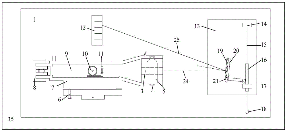
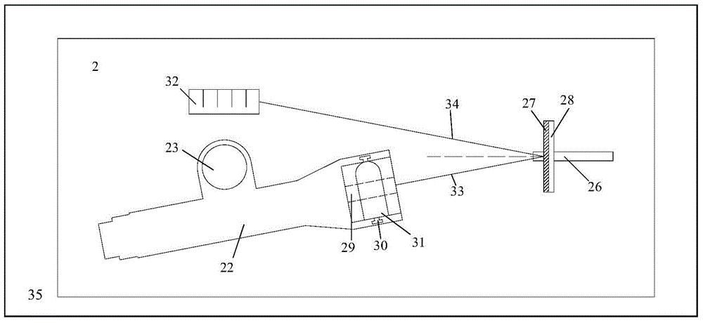
[0024] The structure of the optical lever telescope demonstration device of the present invention is that the demonstration device includes a complete set of two parts, and the back of the complete set of device is equipped with a magnet, which can be adsorbed on a blackboard with an iron backboard. The first part is used to demonstrate the side view optical path of the optical lever telescope system and the mechanical structure of the telescope, and the second part is used to demonstrate the top view optical path of the optical lever telescope system.

[0025] The side view device 1 of the optical lever telescope demonstration device of the present invention includes a side view laser 3, a side view adjustment screw 4, a side view power supply box 5, a pitch screw 6, a telescope side view frame 7, an eyepiece model 8, a...


PUM


Abstract

The invention provides an optical lever telescope presentation device which comprises a complete unit composed of a side view device and a top view device. A magnet is arranged on the back of the complete unit so that the complete unit can be attracted to a blackboard with an iron back plate. The side view device is used for demonstrating the side view light path of an optical lever telescope system and a mechanical structure of a telescope. The top view device is used for demonstrating a top view light path of the optical lever telescope system. The optical lever telescope presentation device has the advantages that the light path principle and the mechanical principle of the optical lever telescope system can be dynamically demonstrated, the light paths are clear, the effect is visual, operation is convenient, and the optical lever telescope presentation device is suitable for teaching explanation in laboratories of schools and demonstration of principles, operation and matters needing attention in actual experiments. Students can deeply understand the working principle of an optical lever system and know clearly about experiment operation skills, and a foundation is laid for skilled operation. All components of the complete unit are magnetic and can be flexibly arranged and attracted to the blackboard or a whiteboard, and therefore the optical lever telescope presentation device is not limited by space.

Description

technical field [0001] The invention relates to a teaching instrument, in particular to an optical lever telescope demonstration device Background technique [0002] The optical lever telescope system is an optical instrument commonly used in teaching experiments. The principle and operation of the system are important teaching contents in many experimental courses, especially in physics experiment courses. However, in the teaching process, students are often difficult to understand the abstract optical path, and they cannot intuitively feel the mechanical structure of the system. Teachers can't reflect the dynamic changes only by drawing the optical path diagram, which leads to students' operation errors due to lack of understanding during the experiment. As a result, the equipment is damaged and the teaching effect is not ideal. Contents of the invention [0003] Aiming at the deficiencies in the prior art, the object of the present invention is to provide a demonstrati...

Claims


Application Information

Patent Timeline
Patent Type & Authority Patents(China)
IPC IPC(8): G09B23/22
CPCG09B23/22
Inventor 杨广武朱飞江越马骏袁嵩博
Owner TIANJIN CHENGJIAN UNIV
Learn More