
Stamping mold and workpiece positioning device thereof

A technology of positioning device and stamping die, applied in the field of stamping die, can solve the problems of wasting die space, increasing production cost, complex structure, etc., and achieving the effects of reducing production cost, avoiding waste of space, and simplifying structure

Active Publication Date: 2015-07-22
ANHUI JIANGHUAI AUTOMOBILE GRP CORP LTD
View PDF7 Cites 5 Cited by
  • Summary
  • Abstract
  • Description
  • Claims
  • Application Information

AI Technical Summary

Problems solved by technology

[0006] However, the existing positioning device uses a positioning plate positioning method, which needs to realize the movement of the positioning plate through a relatively large four-bar linkage structure (that is, a rotating mechanism). The device is large in size and complex in structure, which not only increases the production cost, but also wastes Die space; at the same time, the positioning device needs to judge the timing of avoidance manually, which is greatly affected by the experience of the operator. Slow avoidance will cause interference with the upper mold and related working components, and the return avoidance accuracy of the positioning device is low

Method used


Image

  • Stamping mold and workpiece positioning device thereof
  • Stamping mold and workpiece positioning device thereof
  • Stamping mold and workpiece positioning device thereof

Examples


Embodiment Construction

[0041] The core of the present invention is to provide a workpiece positioning device for a stamping die, which is expected to have a relatively simple structure and a small volume, thereby reducing production costs and avoiding waste of die space. Another core of the present invention is to provide a stamping die including the above workpiece positioning device.

[0042] In order to enable those skilled in the art to better understand the technical solutions of the present invention, the present invention will be further described in detail below in conjunction with the accompanying drawings.

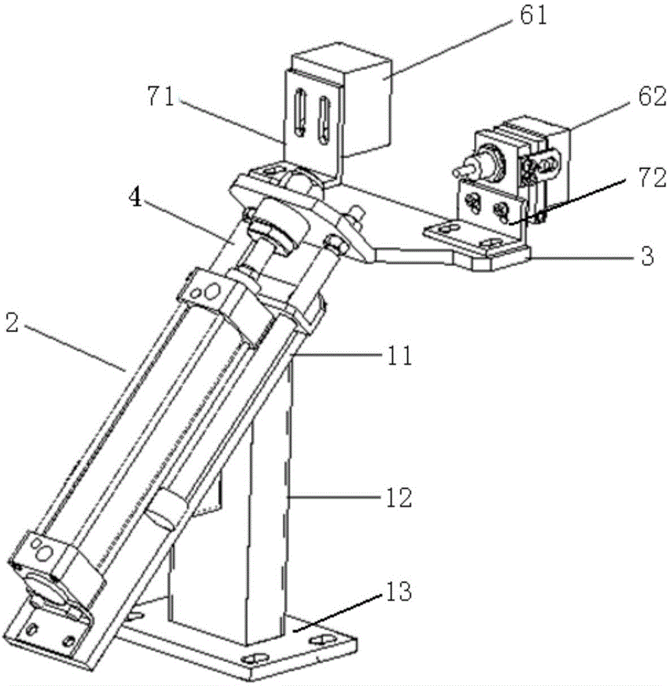
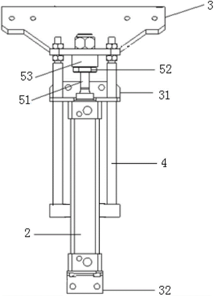
[0043] like Figure 2-6 As shown, in a specific embodiment, the workpiece positioning device provided by the present invention is used for stamping dies, and the workpiece positioning device includes a mounting bracket 1 fixed to the lower mold base, and the mounting bracket 1 includes an inclined mounting plate 11. The fixed portion of the telescopic cylinder 2 is fixedly connected w...


PUM


Abstract

The invention discloses a stamping mold and a workpiece positioning device thereof. The workpiece positioning device comprises a mounting support which is fixed on a lower mold base, the mounting support comprises a mounting plate which is obviously arranged, a fixed part of a telescopic cylinder is fixedly connected with the mounting plate, and a positioning plate is mounted at a telescopic part of the telescopic cylinder; the positioning plate comprises a telescopic cylinder connecting section and a positioning component connecting section, the telescopic part of the telescopic cylinder is mounted at the telescopic cylinder connecting section, a positioning component is mounted at the tail end of the positioning component connecting section, the positioning component connecting section is horizontally arranged, and a preset obtuse angle is formed between the telescopic cylinder connecting section and the positioning component connecting section. Thus, due to the arrangement of the positioning plate with a bent structure, when the telescopic cylinder expands and contracts in an oblique direction, the horizontal motion of the positioning component can also be ensured. Compared with the prior art, the use of a complex four-link structure is avoided, the structure of the positioning device is further simplified, the volume is reduced, the production cost is further reduced, and the waste of space of the mold is avoided.

Description

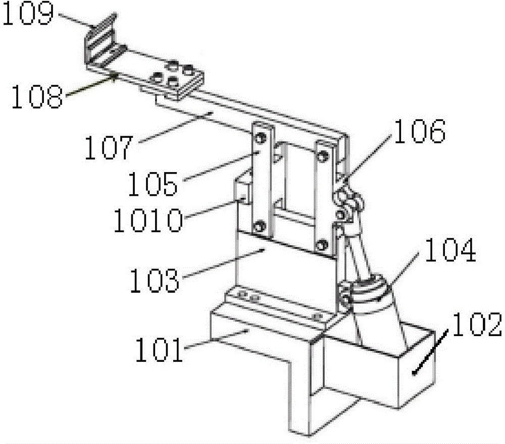
technical field [0001] The invention relates to the technical field of stamping dies, in particular to a workpiece positioning device for stamping dies. The present invention also relates to a stamping die comprising the above workpiece positioning device. Background technique [0002] In the process of vehicle panel processing, stamping dies are widely used, and the positioning device plays a very important role in the stamping die. It needs to ensure that the parts can be accurately positioned before the stamping work, and avoid contact with the upper part during the stamping work. interference with the mold and related working components. [0003] Please refer to figure 1 , figure 1 It is a structural schematic diagram of a positioning device in the prior art. [0004] The positioning device includes a fixed frame 101 installed on the lower mold base, a protective box 102 is arranged on the side of the fixed frame 101, a base 103 is installed on the fixed frame 101, t...

Claims


Application Information

Patent Timeline
IPC IPC(8): B21D37/10B21D43/00
CPCB21D37/10B21D43/003
Inventor 何鹏申陈世涛赖荣胜李昂
Owner ANHUI JIANGHUAI AUTOMOBILE GRP CORP LTD
Learn More